BFGoodrich
Avionics Systems, Inc.
Component
Maintenance Manual
P/N
501-1075-()
PS-823A,
B,
E,
and
F Notes:
PS-823A/T,
B/T,EIT,
and F/TNotes:
Description
of
Notation
orModification
I
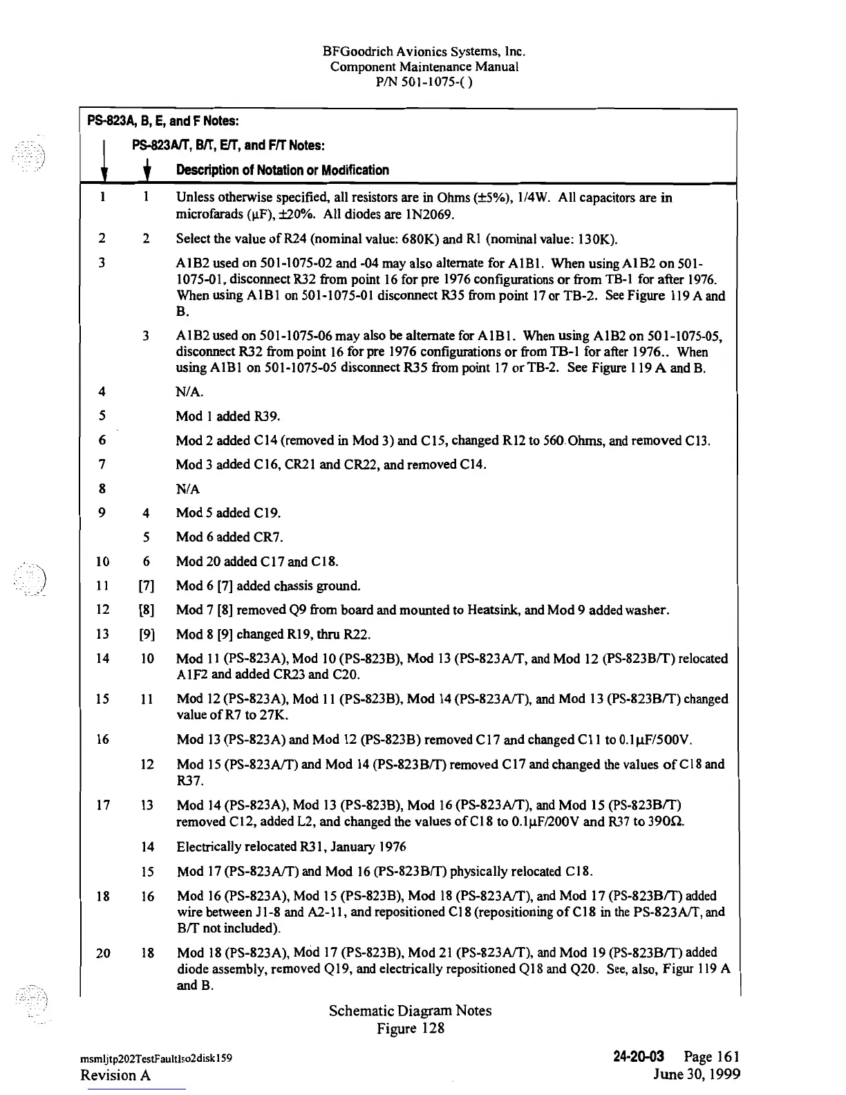
1 Unless otherwise
specified,
all resistors
are in
Ohms
(±5%),
1/4W. All
capacitors
are in
microfarads (µF), ±20%. All
diodes
are
1N2069.
2
2
Select the
value of R24 (nominal value:
680K)
and Rl
(nominal value:
130K).
3
A1B2
used on
501-1075-02
and
-04
may also
altemate
for AlBl. When
using
A1B2
on
501-
1075-01,
disconnect
R32 from point 16 for
pre
1976
configurations or from
TB-1
for
after
1976.
When
using
A1B1
on
501-1075-01
disconnect R35
from
point
17or
TB-2.
See
Figure
119
A
and
B.
3
A l B2 used
on
501-1075-06
may
also be
altemate
for A
lB l. When using
A lB2 on
50 1-1075-05,
disconnect
R32
from point
16 for
pre 1976 configurations
or
from
TB-l
for
after
1976..
When
using
AlBl
on
501-1075-05
disconnect
R35 from
point 17
or
TB-2.
See
Figure 119 A and B.
4 N/A.
5
Mod
1 added R39.
6 Mod 2 added
Cl4 (removed
in
Mod
3)
and
Cl5,
changed Rl2
to
560
Ohms, and
removed
Cl3.
7
Mod
3
added
C16,
CR21
and
CR22,
and removed
Cl4.
8
N/A
9
4
Mod
5 added Cl9.
5
Mod
6
added CR7.
10
6
Mod 20 added C17 and C18.
ll
[7]
Mod
6
[7]
added chassis ground.
12
[8]
Mod
7 [8]
removed
Q9from board and mounted to
Heatsink, and
Mod 9 added washer.
13
[9]
Mod 8 [9] changed R19, thru R22.
14
10
Mod 11
(PS-823A),
Mod
10
(PS-823B),
Mod 13
(PS-823A/T,
and
Mod
12
(PS-823B/T)
relocated
AlF2 and added CR23 and
C20.
15 11
Mod
l2
(PS-823A),
Mod
11
(PS-823B),
Mod 14
(PS-823A/T),
and
Mod 13
(PS-823BTT)
changed
value
of R7
to
27K.
16 Mod
13
(PS-823A)
and
Mod 12
(PS-823B)
removed
Cl7 and changed C11 to
0.1µF/500V.
12
Mod 15
(PS-823A/T)
and Mod 14
(PS-823B/T)
removed
C17 and changed the
values of C18
and
R37.
17 13
Mod 14
(PS-823A),
Mod 13
(PS-823B),
Mod 16
(PS-823A/T),
and Mod
15
(PS-823BTT)
removed
Cl2,
added
L2, and
changed
the
values
of
C18
to
0.1µF/200V and
R37to
390R.
14 Electrically
relocated
R31,
January
1976
15
Mod 17
(PS-823A/T)
and
Mod 16
(PS-823B/T)
physically
relocated Cl8.
18 16
Mod 16
(PS-823A),
Mod
15
(PS-823B),
Mod 18
(PS-823A/T),
and
Mod
17
(PS-823BTT)
added
wire between
11-8
and
A2-1l,
and
repositioned Cl8
(repositioning
of C18
in
the
PS-823ATT,
and
B/T
not included).
20
18
Mod 18
(PS-823A),
Mod 17
(PS-823B),
Mod 21
(PS-823A/T),
and
Mod 19
(PS-823BTT)
added
diode
assembly,
removed
Ql9, and electrically
repositioned
Ql8
and Q20.
See,
also,
Figur 119 A
and B.
Schematic Diagram Notes
Figure 128
msmljtp202TestFaultlso2diskl59
24-20-03
Page 161
Revision
A
June 30, 1999
 Loading...