u¥Uooarlen
Aviomes
systems,Inc.
Component Maintenance Manual
P/N
501-1075-()
1
2 3
4
5 6 7 8 9
10
EMERGEN
POWE
SUPPLY
CONNECTORPINS
IS
MPERES
20 19
18
17 16 15 14 13 12 ll
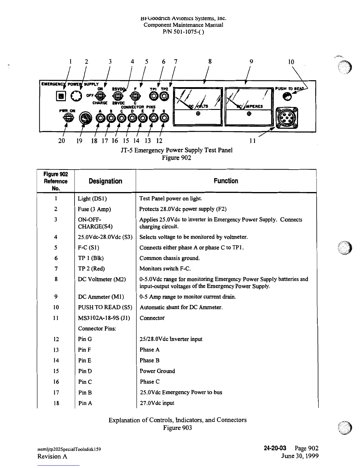
JT-5
Emergency
Power
Supply
Test Panel
Figure 902
Figure902
Reference
Designation
Function
No.
l Light (DS1)
Test Panel power on light.
2 Fuse
(3 Amp)
Protects 28.0Vde
power
supply (F2)
3
ON-OFF-
Applies 25.0Vde to inverter in Emergency Power
Supply. Connects
CHARGE(S4) charging
circuit.
4
25.0Vde-28.0Vde
(S3)
Selects
voltage
to
be
monitored by voltmeter.
5
F-C
(Sl)
Connects either phase
A or
phase
C
to
TPl.
6 TP l
(Bik)
Common chassis ground.
7
TP 2
(Red)
Monitors
switch
F-C.
8 DC Voltmeter (M2)
0-5.0Vde
range
for monitoring Emergency
Power
Supply
batteries and
input-output
voltages
of the
Emergency
Power
Supply.
9 DC Ammeter (Ml)
0-5
Amp
range to
monitor current
drain.
10 PUSH TO READ (S5)
Automatic
shunt for DC
Ammeter.
ll
MS3102A-18-9S
(Jl)
Connector
Connector
Pins:
12 Pin
G
25/28.0Vde Inverter input
13
Pin
F
Phase A
14
Pin
E
Phase B
15
Pin
D
Power Ground
16 Pin
C
Phase C
17 Pin B
25.0Vde
Emergency Powerto bus
18
Pin
A
27.0Vde input
Explanation of Controls, Indicators,
and Connectors
Figure
903
msmljtp202SpecialToolsdiskl59
24-20-03
Page 902
Revision
A
June
30,
1999
 Loading...