BFGoodrich
Avionics
Systems,
Inc.
Component Maintenance Manual
P/N
501-1075-()
23
4
5
6 7
8 9
TEST
SET ADAPTEA
INTLOAD
INTLOAD
ON
7n
MNT
LOAD•¡
N/L
2SV I
l
13
12
11
10
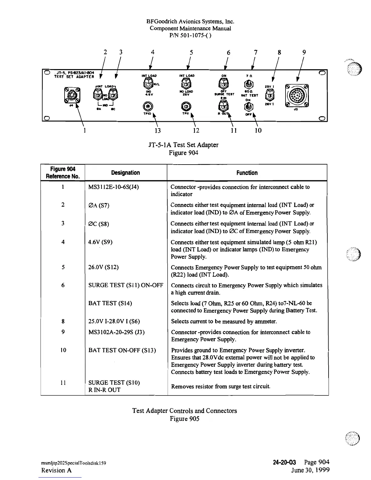
JT-5-lA
Test Set
Adapter
Figure
904
Figure904
Designation Function
Reference
No.
1 MS3112E-10-6S(J4)
Connector
-provides
connection
for
interconnect cable to
indicator
2
ØA (S7)
Connects either test equipment
internal
load(INT Load)
or
indicator load (IND)
to ØA of Emergency Power
Supply.
3
ØC
(S8)
Connects either test equipment
internal
load(INT Load)
or
indicator load (IND) to
ØC of Emergency
Power Supply.
4
4.6V (S9) Connects
either
test equipment
simulated
lamp(5 ohm
R21)
load (INT Load) or
indicator
lamps (IND)
to
Emergency
Power Supply.
5 26.0V
(S12) Connects Emergency Power
Supply to
test equipment 50 ohm
(R22)
load (INT Load).
6
SURGE TEST
(S11)
ON-OFF
Connects circuit to
Emergency
Power Supply
which
simulates
a high
current drain.
BAT TEST
(Sl4)
Selects load
(7
Ohm,
R25 or
60 Ohm, R24)
to7-NL-60
be
connected to Emergency
Power
Supply during
Battery
Test.
8
25.0V
I-28.0V
I (S6)
Selects current to
be measured
by
ammeter.
9
MS3102A-20-29S
(J3) Connector
-provides
connection for
interconnect cable
to
Emergency Power Supply.
10 BAT TEST
ON-OFF
(Sl3)
Provides
ground to Emergency Power
Supply
inverter.
Ensures that
28.0Vdc
extemal
power will
not
be applied
to
Emergency Power Supply
inverter during
battery
test.
Connects battery test loads
to
Emergency
Power Supply.
11 SURGE
TEST (S10)
Removes
resistor from surge test
circuit.
R
IN-R
OUT
Test
Adapter Controls and Connectors
Figure
905
msmljtp202SpecialToolsdiskl59
24-20-03
Page
904
Revision
A
June
30,
1999
 Loading...