July 2020
Installation, Operation and Maintenance Manual
MAN 573 Rev. 8
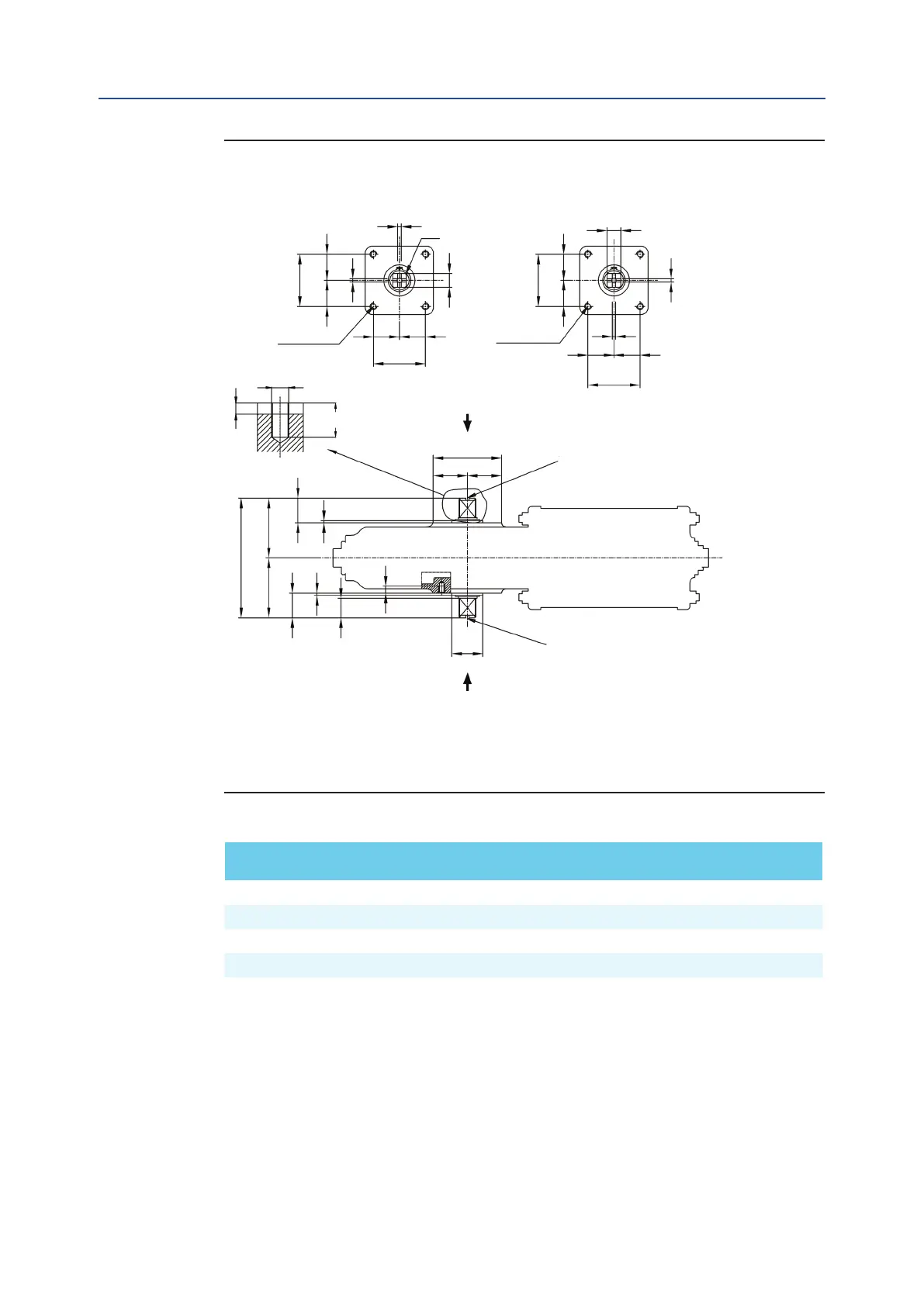
Figure 8 "RP" Pneumatic Actuators Coupling Dimensions - Overall Dimensions
Table 3. Dimensions in mm
RP 13-14-15 49,5 49,5 M8 10 16 21 23 66 30 2,7 140 40 M6 4
RP 30 72,1 72,1 M10 12 22 29 25 92 32 2,7 164 50 M6 4
RP 60 88,4 88,4 M12 15 28 37 34 112 42 3,0 204 60 M6 4
RP 120 99,0 99,0 M16 23 37 49 45 132 55 3,0 270 75 M6 4
Both the actuator anges can be used for valve coupling or the mounting of ancillary equipment
(positioner, limit switch box, etc.).
* UNI 3221
Actuator
Model
A
± 0,2
B
± 0,2
ØC D
ØE
ØF G ØH K J L ØM ØN* R
0
-0,1
0
-0,5
0
-0,2
+0,1
0
View from X View from Y
№4 threaded
holes
№4 threaded
holes
Threaded hole ØN
Joint detail
Threaded hole ØN
X
Y
A
R
R
R
R
A
K
K
=
=
=
=
=
=
=
=
=
=
=
=
B
12
4
B
L
J
J
G
D
ØM
ØF
M6
ØE
ØH
ØC
ØC
ØE
+ 0,5
0
Installation
10
Section 2: Installation

 Loading...


