EasyManua.ls Logo

Binder KB 400 (E6) User Manual

Default Icon
149 pages
To Next Page IconTo Next Page
Page #1 background imageLoading...
Page #1 background image
Issue 02/2017 Art. No. 7001-0307
Operating Manual
Translation of the original operating manual
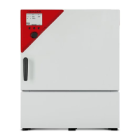
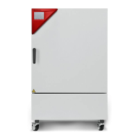
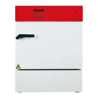
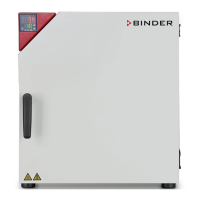
KB (E4), KB (E6)
Cooling Incubators
with compressor technology and program control
Model Model version Art. No.
KB 53 (E4) KB053-230V 9020-0199, 9120-0199
KB 53-UL (E4) KB053UL-120V 9020-0302, 9120-0302
KB 115 (E4) KB115-230V 9020-0397, 9120-0397
KB 115-UL (E4) KB115UL-120V 9020-0398, 9120-0398
KB 240 (E6) KB240-230V 9020-0202, 9120-0202
KB 240-UL (E6) KB240UL-120V 9020-0304, 9120-0304
KB 400 (E6) KB400-230V 9020-0203, 9120-0203
KB 400-UL (E6) KB400UL-120V 9020-0305, 9120-0305
KB 720 (E6) KB720-230V 9020-0204, 9120-0204
KB 720-UL (E6) KB720UL-240V 9020-0306, 9120-0306
BINDER GmbH
Address Post office box 102
78502 Tuttlingen, Germany
Tel. +49 7462 2005 0
Fax +49 7462 2005 100
Internet http://www.binder-world.com
E-mail info@binder-world.com
Service Hotline +49 7462 2005 555
Service Fax +49 7462 2005 93 555
Service E-Mail service@binder-world.com
Service Hotline USA +1 866 885 9794 or +1 631 224 4340 x3
Service Hotline Asia Pacific +852 390 705 04 or +852 390 705 03
Service Hotline Russia and CIS +7 495 98815 16

Table of Contents

Questions and Answers:

Binder KB 400 (E6) Specifications

General IconGeneral
BrandBinder
ModelKB 400 (E6)
CategoryAccessories
LanguageEnglish

Summary

Safety

General Safety Instructions

Core safety guidelines for installing and operating the chambers.

Intended Use

Defines the proper applications and purpose of the cooling incubators.

Measures to Prevent Accidents

Outlines manufacturer's measures to prevent ignition, explosions, and other hazards.

Chamber Description

Instrument Panel

Details the components and functions of the main control panel.

Delivery, Transportation, Storage, and Installation

Location of Installation and Ambient Conditions

Specifies requirements for the installation site and environmental conditions.

Installation of the Equipment

Electrical Connection

Details on connecting the chamber to the power supply and safety precautions.

Start Up

T4.12 Chamber Controller Overview

Operating Modes

Describes the different modes of operation for the chamber controller.

Activating Control Off or Fixed Value Mode

Guide to switching between controller operating modes.

Configuration of Optional Equipment

Set-Point Entry in Fixed Value Mode

Entering Set-points via Quick Menu

Step-by-step guide to entering set-points using the quick menu.

Entering Set-points via General Menu

Instructions for setting temperature and fan speed via the general menu.

Time Programs

Starting and Running Time Programs

Procedure for starting and executing an existing time program.

Creating a New Time Program

Step-by-step guide for creating a new time program with sections.

Set-point Ramp and Step Modes

Explains ramp and step modes for temperature transitions in programs.

Week Programs

Starting and Running Week Programs

Procedure for starting and executing an existing week program.

Creating a New Week Program

Guide to creating a new week program with shift points.

Temperature Setpoint Entry

Details on setting the temperature value for each section in a week program.

Key Lock Functionality

Directly Activating Key Lock

How to immediately activate the key lock feature on the controller.

Automatic Key Lock Configuration

Setting up the automatic activation of the key lock function.

Changing the Password

Procedure for changing the password to unlock the key lock function.

General Controller Settings

Setup Wizard

Sequentially guides through essential controller configuration steps.

Network Configuration

Settings for connecting the chamber to a network via Ethernet interface.

Data Transfer via USB

Exporting Data to USB Drive

Instructions for transferring data from the chamber to a USB storage device.

Importing Data from USB Drive

Procedure for loading data from a USB storage device into the chamber.

Notifications and Alarms

Alarm Status

Describes the three states an alarm message can appear in.

Confirming a "Set" Alarm

Procedure for acknowledging an active alarm on the controller.

Graphical Display of Measured Values

Temperature Safety Devices

Overtemperature Safety Controller (Class 3.1)

Details the electronic controller for overtemperature protection.

Setting the Safety Controller

Instructions for adjusting the safety controller's mode and set-point.

Over- and Undertemperature Safety Controller (Class 3.3)

Describes the optional controller for combined over/undertemperature protection.

Maintenance, Cleaning, and Service

Maintenance Intervals and Service

Guidelines for regular maintenance, service requirements, and warranty.

Cleaning and Decontamination

Procedures for cleaning and decontaminating the chamber safely.

Troubleshooting

Related product manuals