Service documentation series KB/KBF
BB / JTU 25.06.2000
Description C)
Humidity demand is given out from the process controller types DICON 1000/1001 (= D2 and PD2) as
a binary signal 0V or 24V to the control side of the two solid state relays for the electrode current path
(see wiring diagram KBF).
0V = no humidity demand
24V = steam production necessary
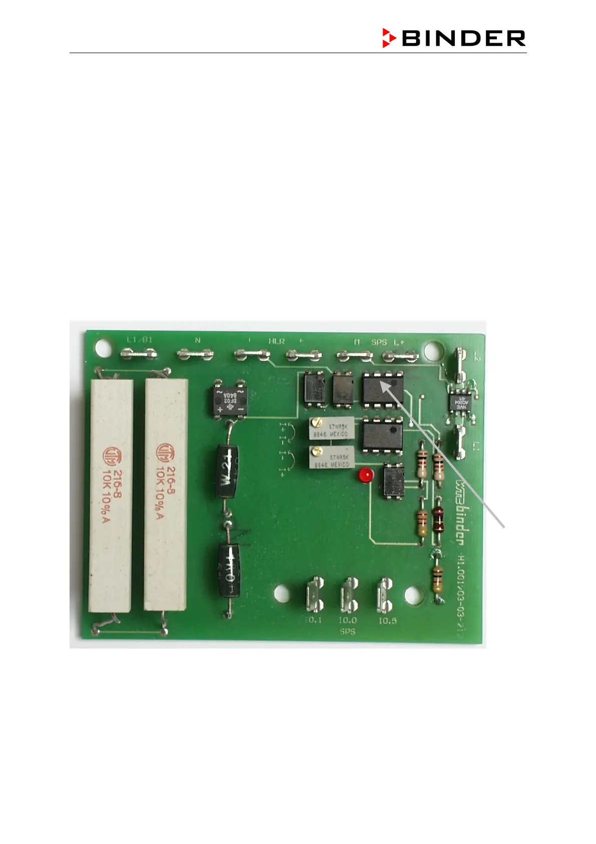
The binary signal is taken there and gets via plug connector HLR + and – to the BINDER humidity
board.
The Binder Humidity Board switches +24V on plug connector SPS I 0.0 as message for the SPS that
there is a humidity demand.
*
L1/B1 N - HLR +HLR M SPS L+
230V AC < 24V power supply 24V
L2
induction
path
230V AC
L1
Registration outputs to the PLC
+24V DC
I 0.1 max. filling level reached
I 0.0 humidity demand
I 0.5 max. current 2A not reached
 Loading...