Service documentation series KB/KBF
BB / JTU 25.06.2000
*
On this point the ( IC pin 3) the voltage divider between the two adjustment potentiometers
for the max. electrode current can be measured. Default setting is somewhat higher than 12 V.
This voltage divider determines the switching point for the water inlet valve.
The voltage on IC pin 3 and therewith the maximum tolerated electrode current can be
adjusted by turning on one of them.
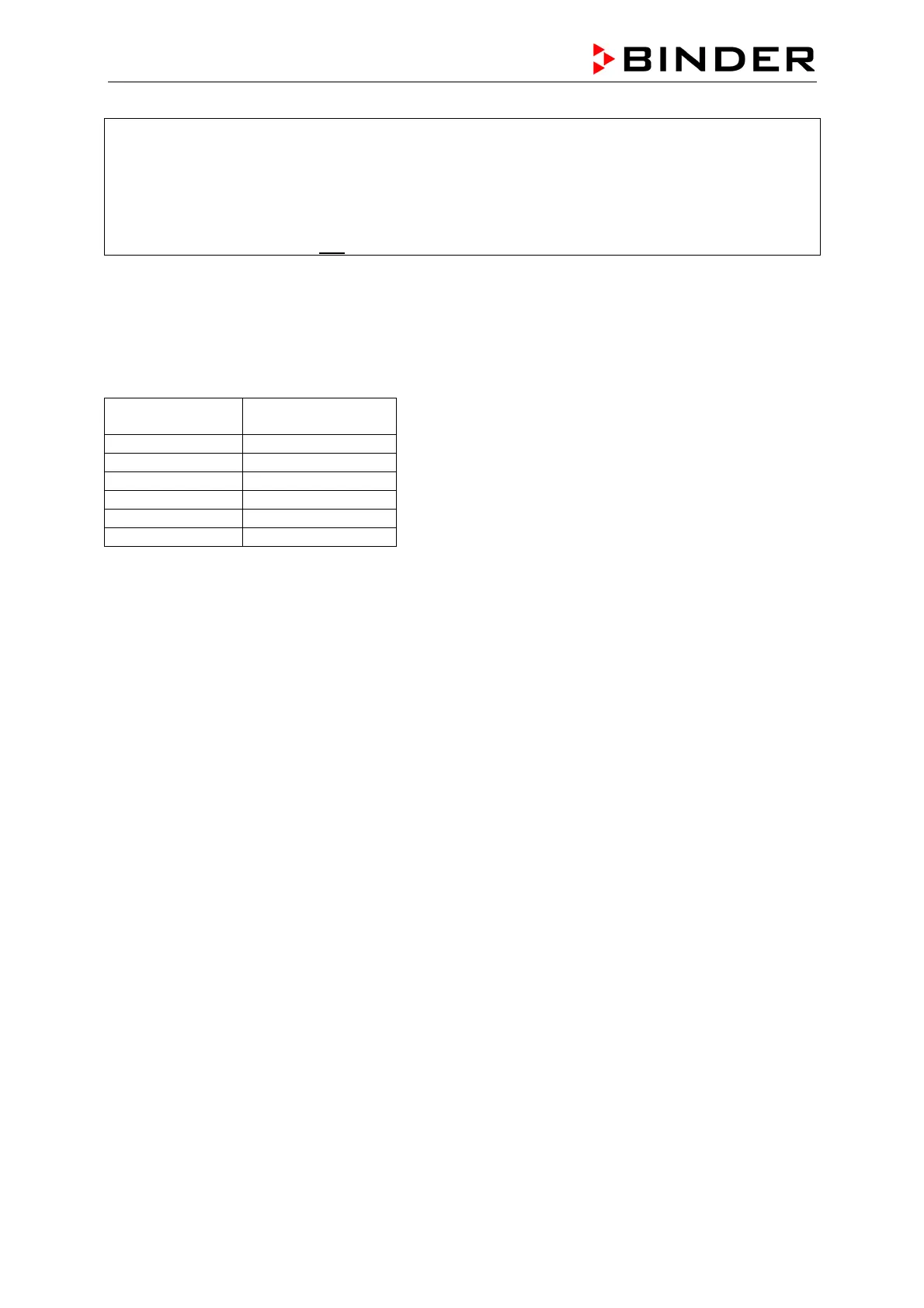
Following table shows the coherence between measured voltages on IC pin 3 and the current through
the electrodes inside the steam cylinder.
Due to the tolerances of the components this values can not be taken as exact ones or all chambers.
But the ratio between difference in current and difference in voltage are constant for all KBF with PLC
and BINDER humidity board. It is round about 0,33V/A.
voltage on pin 3
of the IC *
current through the
steam cylinder
10,5V 1,3A
11,5V 1,7A
12,5V 2,0A
13,5V 2,3A
14,5V 2,6A
 Loading...