Home
Binder
Climate chamber
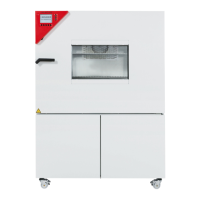
KBF 720
Binder KBF 720 Service Manual
4
of 1
of 1 rating
140 pages
Give review
Manual
Specs
To Next Page
To Next Page
Loading...
KBF (E5
.2
)
Constant climate chambers
with program control
Service Manual
valid f
or the foll
owing model
s of KBF
,
sta
rting wit
h serial no.
09
-
1
1327
:
Model
order no.
KBF 1
15 (E5.2)
9020
-
0139, 9120
-
0139
KBF 1
15
-
UL
(E5.2)
9020
-
0184, 9120
-
0184
KBF 240 (E5
.2)
9020
-
0150, 9120
-
0150
KBF 240
-
UL
(E5.2)
9020
-
0176, 9120
-
0176
KBF 720 (E5
.2)
9020
-
0108, 9120
-
0108
KBF 720
-
UL
(E5.2)
9020
-
0168, 9120
-
0168
Issue 04
-
20
15
order no.
7001
-
0
203
2
Table of Contents
Default Chapter
4
Table of Contents
4
1 Preface
6
General Guidelines
6
Syntax
6
Safety Instructions Structure
7
Warning Levels
7
Safety Symbol
8
Warning Symbols
8
Imperative Symbols
8
Information Symbol
8
2 General Safety Instructions
9
Qualification of Service Personnel
9
Dangers
10
3 Maintenance
12
Safety Check Acc. to DIN VDE 0701-0702
17
4 Troubleshooting
18
General Electrical Faults
19
Faults of the Heating System
21
Faults of the Cooling System
23
Functional Check of the Cooling System
25
Errors in the Humidification Module
27
5 Repair Work at the Housing
34
Replacing the Housing Cover at the Lower Front
34
Replacing the Pen Recorder (-14P1)
35
Replacing the Rear Panel
36
Replacing the Silicone Access Port
37
Replacing the Castors
39
6 Repair Work at the Outer Door
41
Aligning the Outer Door
41
Aligning the Door Hinges
41
Aligning the Adjustable Door Holder Lug with Pulley
42
Checking and Replacing Outer Door Components
43
Dismounting the Interior Side of the Outer Door
43
Replacing the Door Hinge Cover
45
Checking and Replacing the Interior Side of the Outer Door
46
Replacing the Door
48
Replacing the Door Contact Switch (-3S1 )
49
Replacing the Outer Door Gasket
50
Replacing the Triangle Instrument Box
51
Dismantling the Instrument Box
51
Replacing of Components of the Triangle Instrument Box
52
Replacing the Closing Device of the Outer Door
54
7 Repair Work at the Inner and Outer Chamber
56
Replacing the Glass Door
56
Replacing the Closing Device of the Glass Door
57
Replacing the Glass Door Gasket
58
Replacing the Fan (-4M1)
59
Replacing the Frame Gasket
62
Checking and Replacing the Frame Heating Wire (-4E3 )
63
Replacing the Inner Chamber and the Gaskets between the Inner and the Outer Chamber
64
Testing and Replacing the Heating Element (-4E1)
66
Checking and Replacing the Inner Chamber Pt 100 Temperature Sensor (-3B1)
69
Checking and Replacing the Humidity Sensor and the Sensor Board (-3B2)
71
Replacing the Temperature Fuse 110°C / 230°F (-1F2)
74
8 Repair Work at Electric and Electronic Components
75
Activating and Replacing the Miniature Circuit Breaker (-1F1)
76
Replacing the Power Cord with Plug
77
Replacing the Line Filter (-1Z1)
78
Checking and Replacing the Main Switch (-1S1) and the Humidity Switch (-8S1)
79
Removing the Electric Mounting Plates from the Machine Room
80
Components of the Electric Mounting Plate (Standard)
82
Components of the Electric Mounting Plate (Optional Plate)
83
Controller MB1 I/O Board (-3N2)
84
Replacing the Controller MB1 I/O Board (-3N2)
85
Replacing the Controller Display (-3N1)
85
Replacing Individual Mtron Relay Modules
86
Replacing the RS422 / Ethernet Converter (-2U1)
88
Replacing the 24 V Power Supply Unit (-2T1)
89
9 Humidifying and Dehumidifying System
90
Variant a
93
Variant B
104
10 Repair Work at the Cooling System
114
General Information
114
Required Tools for Repairing the Cooling System
114
Replacing the Condenser Fan
115
Replacing the Capillary Tubes
116
Checking the Step Motor Valve (-7Y3)
117
Interface Board IB3 (-7N1) for Step Motor Valve
118
Overview Cooling Cycle
119
11 Calibrating and Adjusting the Temperature and Humidity Control
120
General Execution of the Calibration
120
Calibrating and Adjusting Points
121
Calibrating and Adjusting Point of the Temperature Control
121
Calibrating and Adjusting Points of the Humidity Control
121
Calibrating and Adjusting the Temperature Control
121
Resetting the Temperature Controller Adjustment
122
Calibrating the Temperature Controller
125
Adjusting the Temperature Controller
127
Setting the Door Heating Correction
129
Calibrating and Adjusting the Humidity Controller
130
Resetting the Humidity Controller Adjustment
130
Calibrating the Humidity Controller
131
Adjusting the Humidity Controller
133
12 Spare Parts
134
13 Parts Subject to Wear
138
14 Revision History
138
Other manuals for Binder KBF 720
Operating Manual
161 pages
4
Based on 1 rating
Ask a question
Give review
Questions and Answers:
Need help?
Do you have a question about the Binder KBF 720 and is the answer not in the manual?
Ask a question
Binder KBF 720 Specifications
General
Temperature fluctuation
±0.3 °C
Humidity range
10% to 98% RH
Humidity fluctuation
±1.5% RH
Voltage
230 V
Frequency
50/60 Hz
Interior volume
700 liters
Related product manuals
Binder KBF 720 (E5.2)
103 pages
Binder KBF 240
140 pages
Binder KBF 115
140 pages
Binder KBF 115 (E5.2)
103 pages
Binder KBF P 240 (E5.2)
103 pages
Binder KMF Series
161 pages
Binder BD
19 pages
Binder ED 23
69 pages
Binder FD 53
69 pages
Binder MK 240
159 pages
Binder MK 115
159 pages
Binder FD240-230V
69 pages