5
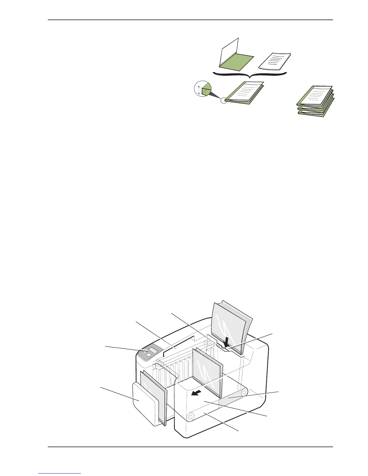
The machine consists of five main parts: Cover selector, Display, Input bay,
Binding unit, and Output tray.
Cover selector
The cover selector comprises a slot into which you
insert the set of papers to be bound, short side first.
A sensor measures the thickness of the set and the
recommended type of cover is then shown on the
display.
Display
The display shows what is happening in the machine. A
number of user functions can be selected using the two
push-buttons on the panel. (See also chapter 5 “User
settings”.)
Input bay
Insert the set of papers into the selected cover. This is
now called a document (cover with a set of papers).
Now put the document into the input bay with the spine
downwards.
If the binding machine stops for some reason, the jam
clearance door in the input bay can be pushed aside
and the document removed. (See also chapter 7
“Clearing and emptying”.)
Binding unit
The document is first jogged and then transported into a
heating zone where the glue in the cover melts. Then
the document passes through a cooling zone, and the
glue binds the pages together in the cover.
Output tray
The output tray moves outwards as the finished
documents are fed into it. An audible signal sounds
when the output bay is nearly full and a message is
shown on the display.
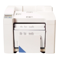
Terminology
In this manual and in the Quick Guide, the Bindomatic
cover is referred to as
cover
and the set of papers is
referred to as the
set
. When the set is put into the
cover, this is referred to as a
document
.
When a number of documents are piled on each other,
this is referred to as a
batch
.
Cover
Set
Batch
Document
Output tray
Input bay
Jam clearance door
Heating zone
Binding unit
Cooling
zone
Display
Cover selector
Spine
width
3. Description