4
SPECIFICATIONS
Maximum WORKING PRESSURE
Universal Hose Connection
Air supply P1 : 7 bar Atomization air: 1 / 4‘’BSP/NPS
Material supply P2 : 7 bar Cylinder air: 1 / 4’’BSP/NPS
Min Cylinder Operating pressure : 4 bar Material: 1 / 4’’BSP/NPS
Maximum service temperature :
40° C
MATERIAL of construction
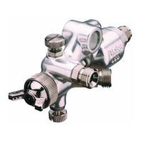
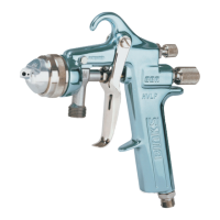
Gun body Aluminum
Tip Stainless steel
Needle Stainless steel
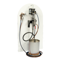
INSTALLATION
IMPORTANT: In order to ensure that this equipment reaches you in first class condition, protective coatings,
rust inhibitors, etc., have been used. Flush all equipment through with a suitable solvent before use to remove
these agents from material passages.
Note: A single hose supplies both atomizing and cylinder air. To prevent un-atomized coating material being
expelled from the nozzle at the end of the spray cycle, all air should be exhausted through the gun. It is
recommended that a two way valve should be fitted in the control line. If a three way valve is used, install a
plug in the exhaust port.
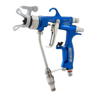
Mount gun using the 12.7mm (1/2") rod or stud diameter and secure with screw 164392
HOSING
Use filtered regulated air supply. The minimum air supply pressure required to operate the cylinder is 4.5 bar
(67 ibf/in²) Connect air supply to connector 184574 indicated by markings “AIR” on the gun body. Connect
coating material to the connector184574 on the gun body.
EARTHING the Spray gun must be earthed to dissipate any electrostatic charges which may be created by
fluid or air flows. This can be achieved through the Spray gun mounting, or conductive air/fluid hoses.
Electrical bond from the spray gun to earth should be checked with an ohmmeter. A resistance of less than 10
6
Ohms is recommended.
WARNING: See instructions under “Replacement of Parts”.
Recommended hose sizes up
To 10m (34ft) long: Air Supply: 8mm (5 /16") bore, Material: 8 mm (5 /16 ") bore.
To 5m (17ft) long: Air Supply: 6mm (1 /4") bore, Material: 6 mm (1 /4 ") bore.