EasyManuals Logo

Bio-Logic SP-200 User Manual

Default Icon
122 pages
To Next Page IconTo Next Page
To Previous Page IconTo Previous Page
Page #62 background imageLoading...
Page #62 background image
Manual for VMP300-based instruments
54
Fig. 77: Screw-on adapters for M8 threaded bolts.
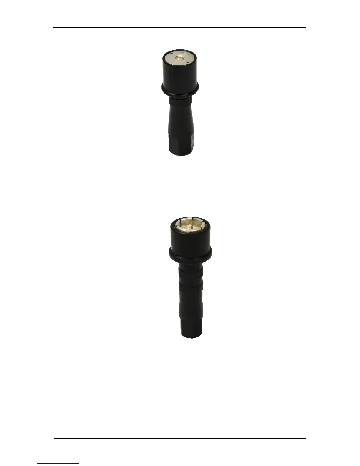
Clamping contact adapter for M12 hex. screw heads. It comes together with S-
SL/PF10x38 safety fuse cable. The axial connection is made by means of a Ø 6mm
coupling socket with locking device.
Fig. 78: Clamping contact adapter for M12 hexagonal screw heads.
5.4 Auxiliary inputs/outputs (DB9)
The following figure shows the structure of the DB9F connector and the different pins that can
be used as auxiliary inputs/outputs.

Table of Contents

Questions and Answers:

Question and Answer IconNeed help?

Do you have a question about the Bio-Logic SP-200 and is the answer not in the manual?

Bio-Logic SP-200 Specifications

General IconGeneral
BrandBio-Logic
ModelSP-200
CategoryMeasuring Instruments
LanguageEnglish

Related product manuals