6.4 External device control and recording
6.4.1 General description
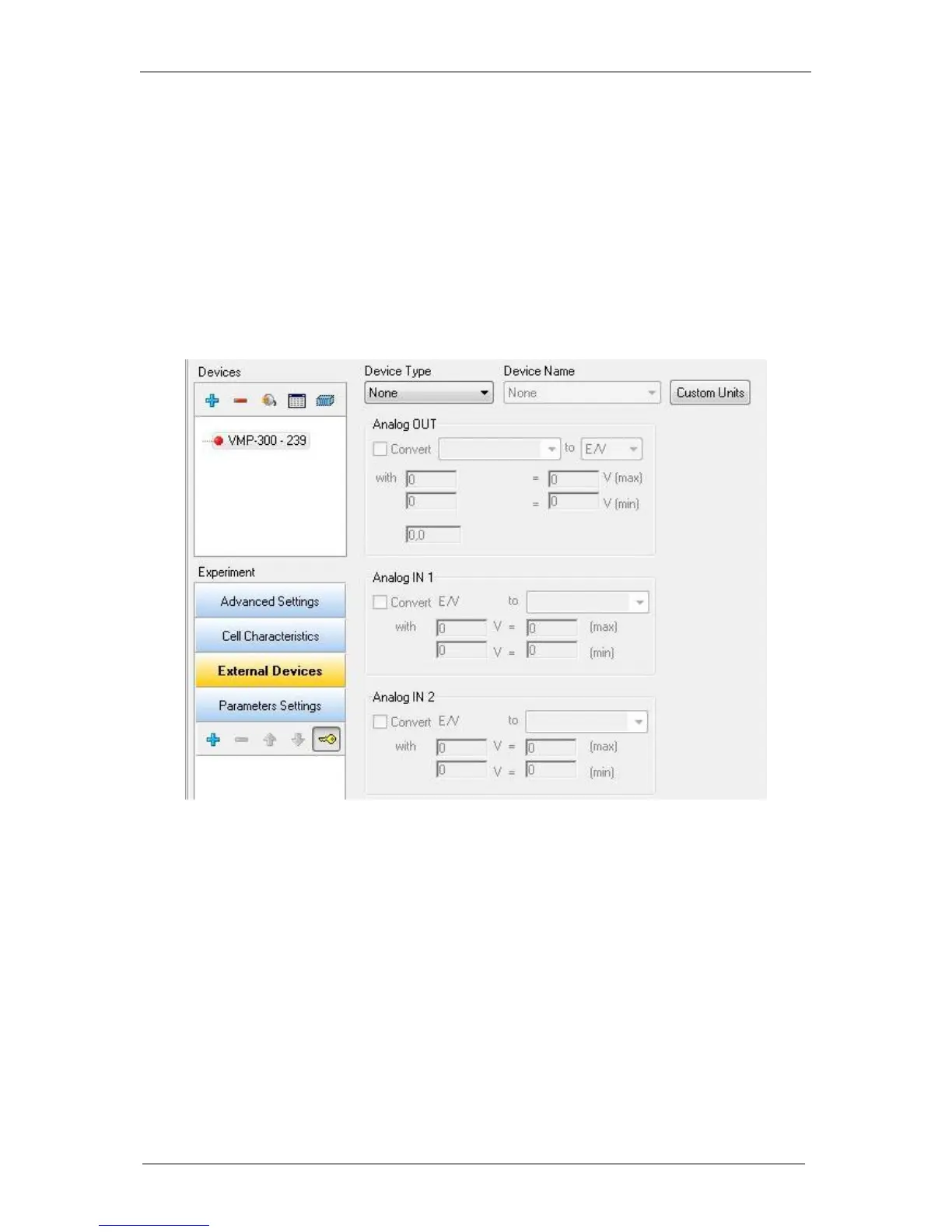
The EC-Lab
software offers the user the ability to control external devices such as rotating
electrodes and thermostatic baths and to record external analog signals through the auxiliary
DB9 connector. The user has to configure the analog output to control an external device and
configure the Analog In1 and Analog In2 inputs to record external signals. Our instruments can
control and record analog signals from – 10 to + 10 V. Most external devices work in a 0 to
+ 5 V range. The figure below shows the external device window where the user sets
parameters. Many instruments are already configured in the software to be controlled by our
potentiostat. This list continues to be expanded in new versions of EC-Lab
software. To
configure external devices select “External Device” frame.
Fig. 83: “External Devices” frame.
The user must define several parameters to configure the external device to either be
controlled via the analog output (left column) or record/measure data via analog input 1 and 2
(right column). The procedure for the configuration of the auxiliary inputs/outputs is described
is as follows:
1- Choose the channel to configure. Each channel can be configured for a specific device.
One channel can control one device and the other one another device.
2- Select the Device Type in the list between None, Thermostat, RDE, QCM and other.
According to the selected device type one or several device names are available.
3- Among the available devices some can be controlled by the analog output and some
of them can only be used to record values with analog inputs 1 and 2. The user must
tick the box to activate the input/output.
4- In the activated frame, the user must define the conversion between the input voltage
and the variable to plot. This is a direct linear conversion in the range defined by the
user between the min and the max value.
5- The user can also define the name and the unit of the variable they want to display.
Click on “Custom Variables”. The figure below is displayed:
 Loading...