60
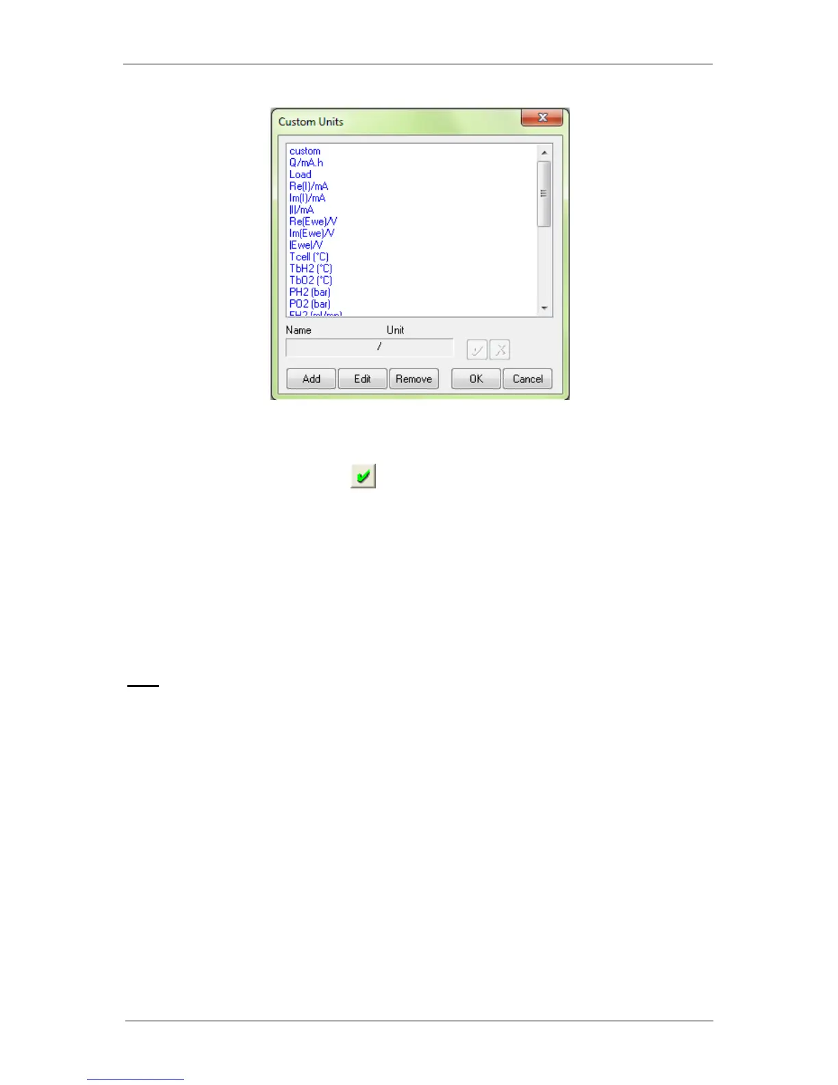
Fig. 84: Custom Units window to define new variables.
To create a new variable with its unit, click on “Add” and put the name and the unit of the new
variable in the frame. Then click on to validate. The new variable is displayed in the list in
blue (as a custom variable) and can now be selected as the recorded variable for the analog
inputs.
6- Finally click on “OK” to configure the selected channel to record the auxiliary input
signal
The new selected variables for Analog In1 and Analog In2 are automatically displayed on the
“Cell characteristics” window and activated for recording. In the “Selector” the created
variables are displayed and can be plotted. These auxiliary variables can be used in several
protocols as conditional limits of an experiment.
Note: - The parameters set in Analog In1 and Analog In2 to define the linear slope can be
inverted to display an inverse relationship between the recorded value and the plotted
value.
- The configuration of external devices that can be controlled by the potentiostat (analog
output) are described in detail in the corresponding sections of the manual.
- A manual control of external devices is also available on the left of the panel.
- When a channel has been configured to control an external device, this device can
be seen in the global view.