7
MODULE INSTALLATION
OPTION A: LID INSTALLATION
1. Apply sealant to the underside of the liner lip and tank lid.
2. Insert the FAST® liner into the opening in the top of the tank lid.
3. Place the unit lid on top of the FAST® liner. Carefully line up the airline
hole in the unit lid with the coupling at the top of the airlift inside the
tank. Make sure the airline pipe stands perpendicular to the lid.
4. Using a hammer drill, drill holes for anchoring the module to the tank
using the preformed holes in the module lid as guides.
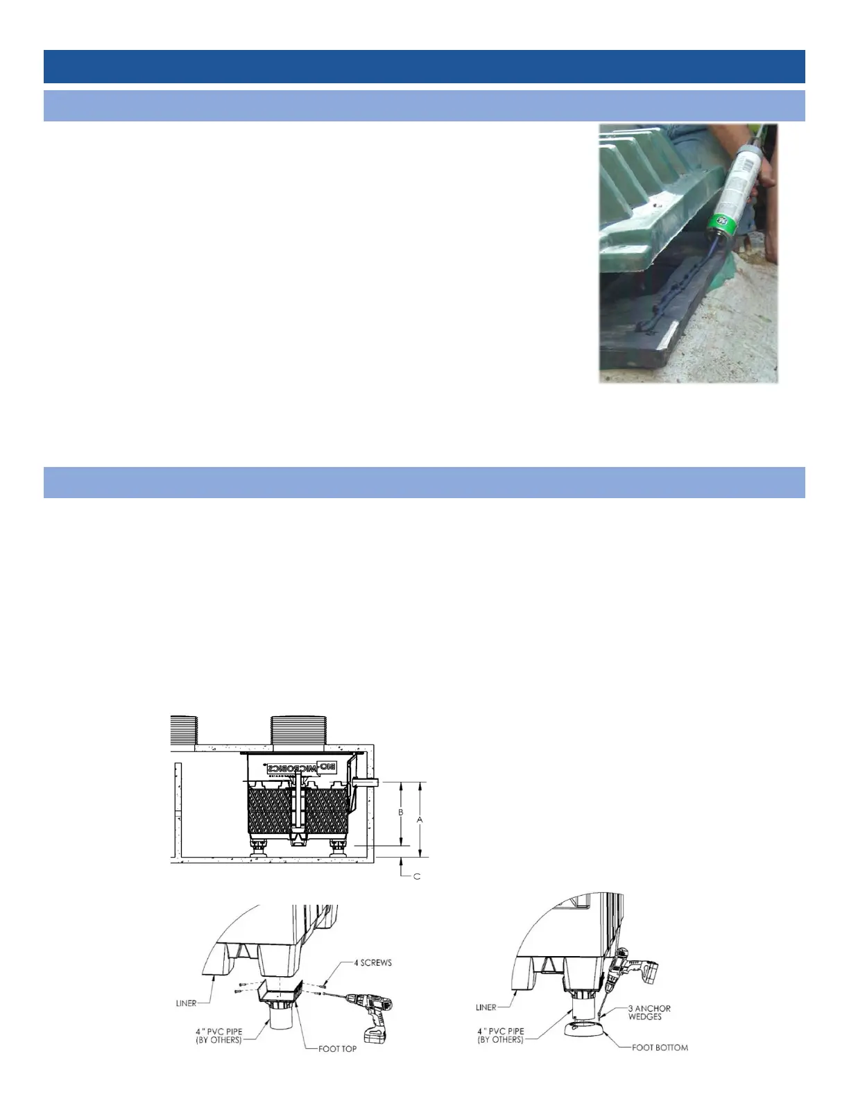
5. Apply sealant (premium wet/dry elastomeric flashing cement) to
surfaces between liner and lid.
6. Place unit lid on top of liner and secure using holes drilled in step 3
with 3/8” stainless steel anchor wedges.
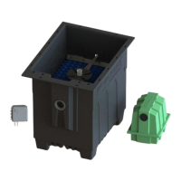
OPTION B: FOOT INSTALLATION
1. Determine length of pipe needed for legs. Glue the pipe to the bottom and top leg pieces. Attach the
leg extensions to the liner using supplied self-tapping screws. Stainless steel hardware is required.
Note: For legs, use 4” [10.1 cm] PVC schedule 40 pipe. If legs are longer than 18” [46 cm], then
schedule 80 PVC or stronger pipe must be used. Consult factory for legs longer than 36” [90 cm].
2. Carefully lower liner into tank using a jib crane or other approved method that meets the lifting weight
of the liner. Secure foot bottom to the base of the tank with stainless steel anchor bolts (not provided).
3. Three anchor wedges are required per leg extension.
To determine pipe length for legs
(dimension C):
A – B – ¼
in [0.64 cm] = C
Where ¼ in [0.64cm] is the thickness of
foot top and foot bottom.