17
SMALL CONTROL PANEL
The smaller FAST® control panels are provided with hinged enclosures. The face of the panel enclosure
features model and serial numbers, power indicator lamp, alarm indicator lamp, alarm silence button, and
blower breaker switch. The electrical details of the control panel are printed on a label affixed to the outside
of the enclosure. The inside of the control panel contains a printed circuit board. The small panels have
terminations for incoming and outgoing power mounted directly on the circuit board. The circuit board also
provides optional power to a UV-light system up to 2 amps. The UV terminals supply the same voltage that is
wired to the board input terminals.
The circuit board has two sets of normally open dry contacts for optional connections such as a float switch or
pressure switch. The normally open contacts will activate the panel alarm when closed. Next to these
contacts are a 12VDC terminal which can be used to power an external dialer device, and an alarm output
terminal which can be used to signal an external device when the panel goes into alarm. The alarm output is a
normally open switch that will close during an alarm condition.
Current Sensors
The small FAST® control panel features two current sensors: (1) the “UV” current sensor, which can be
activated to dedect a failed UV bulb when the current drawn is less than 5 milliamps (activating the panel
alarm), and (2) a blower current sensor, which measures the current used by the blower; it will signal an
alarm if the blower draws less than 0.5 amps. A maximum threshold for blower current will signal an alarm
and is adjustable up to 15 amps.
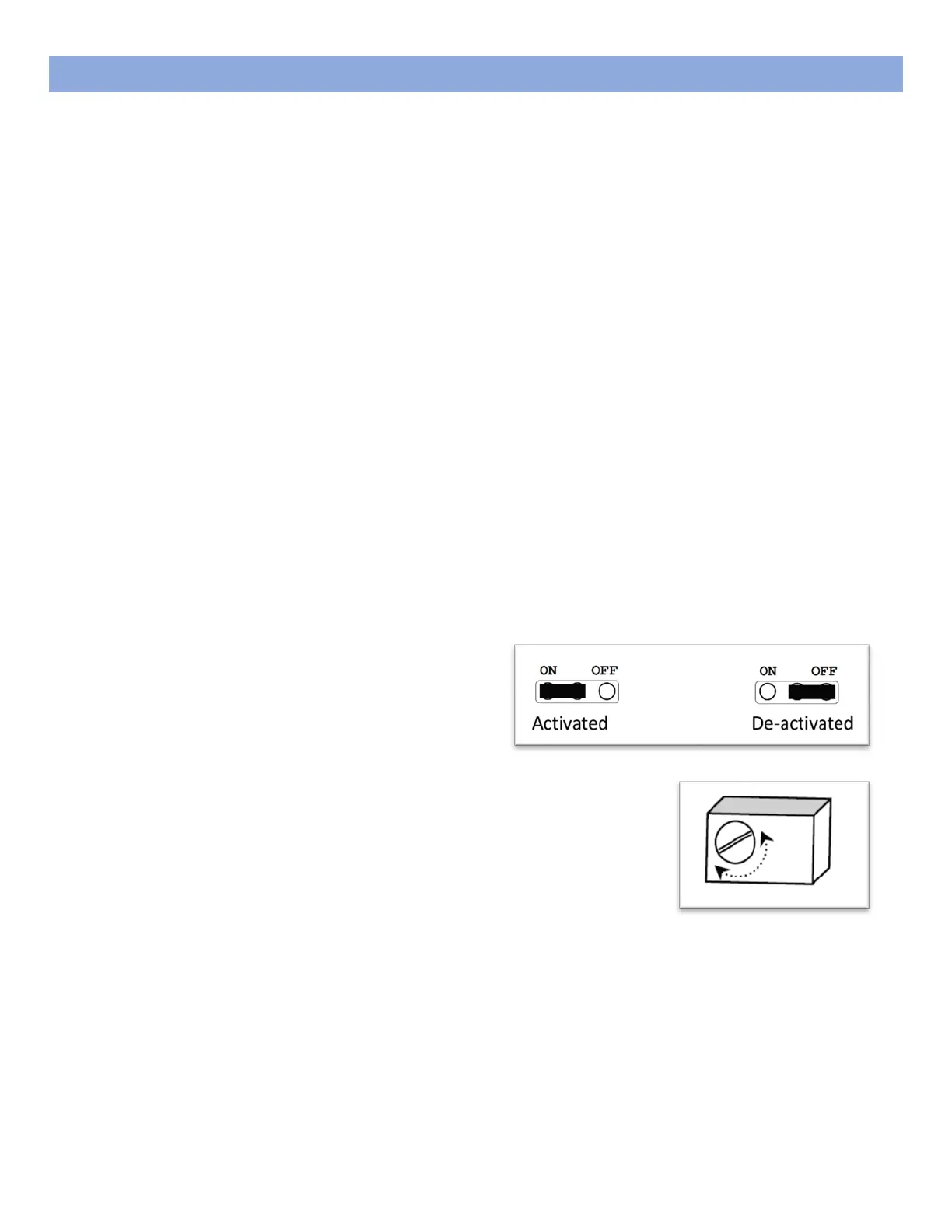
Activate Current Sensor
To activate either the UV current sensor or the
blower current sensor, move the jumper on the
labeled current sensor pins from the right-most
two pins to the left-most two pins, as shown below.
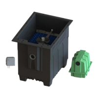
Adjust Current Sensor
To adjust the blower current sensor maximum threshold, turn the small
screw on the front of the sensor clockwise to increase and counter-
clockwise to decrease.
Note: Adjust the blower current sensor at system startup with a full FAST® tank.
In order to properly set the blower current sensor, the FAST® treatment tank must be filled with water to the
normal operating level. With power supplied to the panel and the blower running, adjust the current sensor
up or down until the point at which the alarms starts buzzing or stops buzzing. Once the spot is found, turn
the current sensor screw ¼ to ½ of a rotation clockwise to set the blower current maximum threshold.