1B5*?9B@<1H?>>53C9?>B
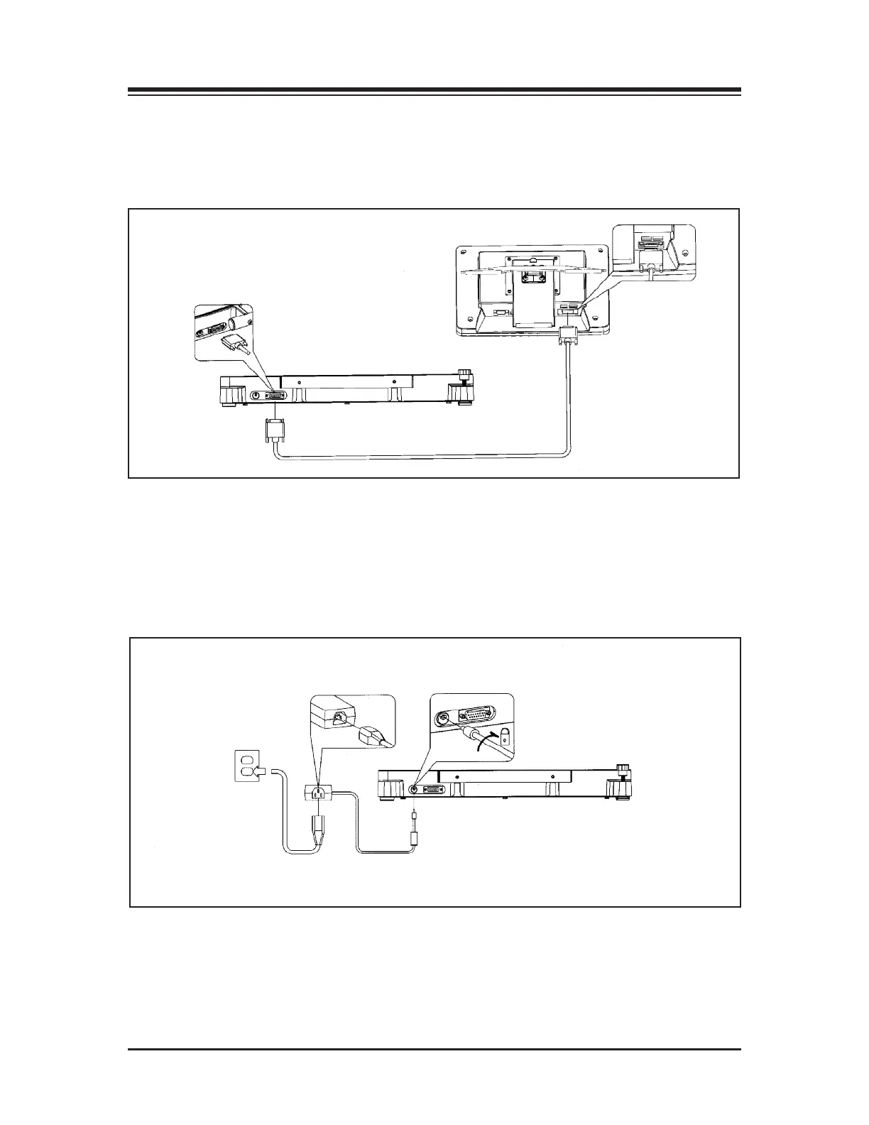
(See Figure 3.4.)
Connect the cable with the 15 pin Female D connector to the display. Connect the 15-pin Male D
connector at the opposite end of the cable to the base.
Figure 3.4. Base to display connections.
&?F5A?>>53C9?>B
(See Figure 3.5.)
Plug the power supply into wall current. Plug the opposite end of the power supply into the
base unit. Insert plug and twist ? turn to lock.
Figure 3.5. AC power connections.
SYSTEM SPECIFICATIONS
CONNECTIONS AND ADJUSTMENTS — 3-2 —