EasyManuals Logo

Biostar A520MH 3.0 User Manual

Biostar A520MH 3.0
142 pages
To Next Page IconTo Next Page
To Previous Page IconTo Previous Page
Page #18 background imageLoading...
Page #18 background image
18 | Chapter 2: Hardware installaon
F_PANEL: Front Panel Header
This connector includes Power-on, Reset, HDD LED and Power LED connecons. It allows user
to connect the PC case’s front panel switch funcons.
Pin Assignment Funcon Pin Assignment Funcon
1 HDD LED(+)
HDD
LED
2 Power LED (+)
Power
LED
3 HDD LED(-) 4 Power LED (-)
5 Ground
Reset
Buon
6 Power Buon
Power-On
Buon
7 Reset Control 8 Ground
9 NC NC 10 NA NA
SPKR: Chassis Speaker Header
Please connect the chassis speaker to this header.
Pin Assignment
1 +5V
2 N/A
3 N/A
4 Speaker
TPM: Trusted Plaorm Module Header
This header allows you to store cryptographic keys that protect informaon.
Pin Assignment Pin Assignment
1 F_LAD0 2 +3V
3 F_LAD1 4 +3V
5 F_LAD2 6 TPM_24MHZ
7 F_LAD3 8 GND
9 L_FRAME_N 10 NC
11 SER_IRQ 12 PLTRST_N
13 CLK_RUN_N 14 +3V3_DUAL

Table of Contents

Questions and Answers:

Question and Answer IconNeed help?

Do you have a question about the Biostar A520MH 3.0 and is the answer not in the manual?
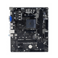
Biostar A520MH 3.0 Specifications

General IconGeneral
Form FactorMicro ATX
ChipsetAMD A520
SocketAM4
Memory Slots2
Max Memory64GB
PCIe Slots1 x PCIe 3.0 x16, 1 x PCIe 3.0 x1
Memory SupportDDR4 3200/ 2933/ 2667/ 2400/ 2133 MHz
Storage Interface4 x SATA III
USB Ports6 x USB 2.0
AudioRealtek ALC887
LANRealtek RTL8111H
Video OutputsHDMI, VGA

Related product manuals