Chapter 2: Hardware installaon | 17
A520MH 3.0
2.7 Headers & Connectors
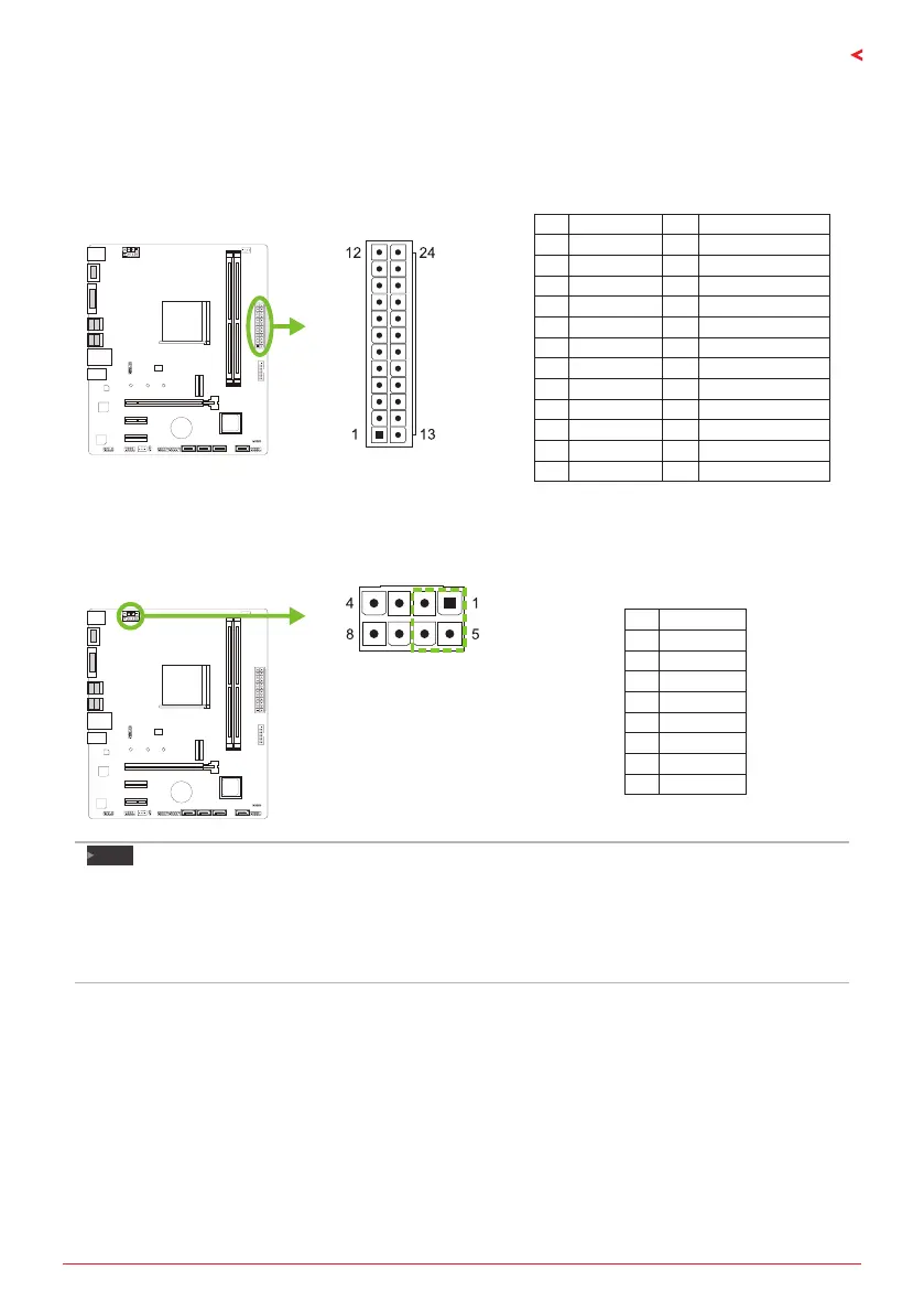
ATX: ATX Power Source Connector
For beer compability, we recommend to use a standard ATX 24-pin power supply for this
connector. Make sure to nd the correct orientaon before plugging the connector.
Pin Assignment Pin Assignment
13 +3.3V 1 +3.3V
14 -12V 2 +3.3V
15 Ground 3 Ground
16 PS_ON 4 +5V
17 Ground 5 Ground
18 Ground 6 +5V
19 Ground 7 Ground
20 NC 8 PW_OK
21 +5V 9 Standby Voltage+5V
22 +5V 10 +12V
23 +5V 11 +12V
24 Ground 12 +3.3V
ATX_12V_2X4: ATX Power Source Connector
The connector provides +12V to the CPU power circuit. If the CPU power plug is 4-pin, please
plug it into Pin 1-2-5-6 of ATX_12V_2X4.
Pin Assignment
1 +12V
2 +12V
3 +12V
4 +12V
5 Ground
6 Ground
7 Ground
8 Ground
Note
»
»
Before you power on the system, please make sure that both ATX and ATX_12V_2X4 connectors
have been plugged-in.
»
»
Insucient power supplied to the system may result in instability or the peripherals not funconing
properly. Use of a PSU with a higher power output is recommended when conguring a system with
more power-consuming devices.
 Loading...