Chapter 2: Hardware installaon | 27
A520MPT-E | A520MPT | A520MT-E | A520MT | A520MS | B550MT | B550MS
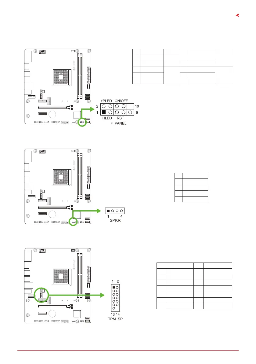
F_PANEL: Front Panel Header
This connector includes Power-on, Reset, HDD LED and Power LED connecons. It allows user
to connect the PC case’s front panel switch funcons.
Pin Assignment Funcon Pin Assignment Funcon
1 HDD LED(+)
HDD
LED
2 Power LED (+)
Power
LED
3 HDD LED(-) 4 Power LED (-)
5 Ground
Reset
Buon
6 Power Buon
Power-On
Buon
7 Reset Control 8 Ground
9 NC NC 10 NA NA
SPKR: Chassis Speaker Header
Please connect the chassis speaker to this header.
Pin Assignment
1 +5V
2 N/A
3 N/A
4 Speaker
TPM: Trusted Plaorm Module Header
This header allows you to store cryptographic keys that protect informaon.
Pin Assignment Pin Assignment
1 F_LAD0 2 +3V
3 F_LAD1 4 +3V
5 F_LAD2 6 TPM_24MHZ
7 F_LAD3 8 GND
9 L_FRAME_N 10 NC
11 SER_IRQ 12 PLTRST_N
13 CLK_RUN_N 14 +3V3_DUAL