EasyManuals Logo

Biostar G41D3 Setup Manual

Biostar G41D3
To Next Page IconTo Next Page
To Previous Page IconTo Previous Page
Page #14 background imageLoading...
Page #14 background image
Motherboard Manual
12
CHAPTER 3: HEADERS & JUMPERS SETUP
3.1 H
OW TO SETUP JUMPERS
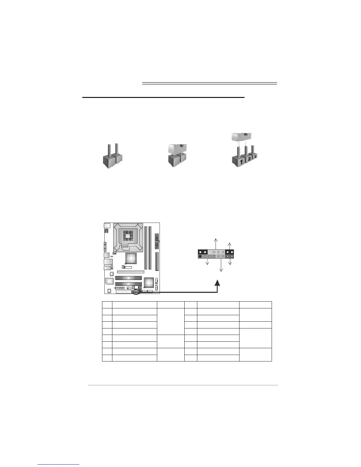
The illustration shows how to set up jumpers. When the jumper cap is
placed on pins, the jumper is “close”, if not, that means the jumper is
“open.
Pin opened Pin closed Pin1-2 closed
3.2 DETAIL SETTINGS
PANEL1: Front Panel Header
This 16-pin connector includes Power-on, Reset, HDD LED, Power LED, and
speaker connection. It allows user to connect the PC case’s front panel switch
functions.
PWR_LED
On/Off
RST
HLED
SPK
++
+
-
-
1
9
8
16
Pin Assignment Function Pin Assignment Function
1 +5V 9 N/A
2 N/A 10 N/A
N/A
3 N/A 11 N/A N/A
4 Speaker
Speaker
Connector
12 Power LED (+)
5 HDD LED (+) 13 Power LED (+)
6 HDD LED (-)
Hard drive
LED
14 Power LED (-)
Power LED
7 Ground 15 Power button
8 Reset control
Reset button
16 Ground
Power-on button

Other manuals for Biostar G41D3

Questions and Answers:

Question and Answer IconNeed help?

Do you have a question about the Biostar G41D3 and is the answer not in the manual?

Biostar G41D3 Specifications

General IconGeneral
Form FactorMicro ATX
ChipsetIntel G41
CPU SocketLGA 775
Memory TypeDDR3
Maximum Memory8 GB
Storage Interface4 x SATA 3Gb/s
USB Ports8 x USB 2.0 (4 rear, 4 via headers)
AudioRealtek ALC662 6-Channel HD Audio
CPU SupportIntel Core 2 Quad, Core 2 Duo, Pentium Dual-Core, Celeron
Memory Slots2 x DIMM
Memory Speed1066/800 MHz
Expansion Slots1 x PCIe x16, 1 x PCI
Rear Panel I/O Ports1 x PS/2 keyboard, 1 x PS/2 mouse, 1 x VGA, 4 x USB 2.0, 1 x RJ-45 LAN, 3 x audio jacks

Related product manuals