Motherboard Manual
18
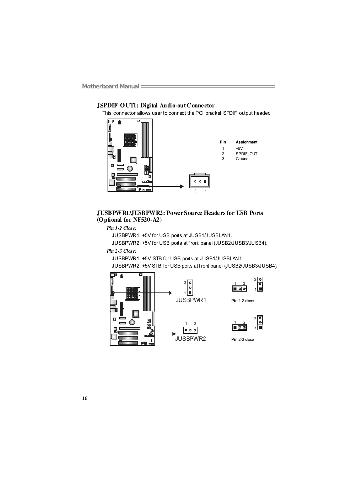
JSPDIF_OUT1: Digital Audio-out Connector
This connector allows user to connect the PCI bracket SPDIF output header.
Pin
Assignment
1 +5V
2 SPDIF_OUT
13
3 Ground
JUSBPW R1/JUSBPW R2: Powe r S ou rce Heade rs for USB Ports
(Optional for NF520-A2)
Pin 1-2 Close:
JUSBPWR1: +5V for USB ports at JUSB1/JUSBLAN1.
JUSBPWR2: +5V for USB ports at f ront panel (JUSB2/JUSB3/JUSB4).
Pin 2-3 Close:
JUSBPWR1: +5V STB for USB ports at JUSB1/JUSBLAN1.
JUSBPWR2: +5V STB f or USB ports at f ront panel (JUSB2/JUSB3/JUSB4).
31
1
3
Pin 1-2 close
1
3
13
JUSBPWR1
JUSBPWR2
3
1
1
3
Pin 2-3 close



 To Next Page