EasyManua.ls Logo

Biostar P4M80-M4 - User Manual

Biostar P4M80-M4
31 pages
Print Icon
To Next Page IconTo Next Page
Loading...
P4M80-M4
i
FCC Information and Copyright
This equipment has been tested and found to comply with the limits of a Class
B digital device, pursuant to Part 15 of the FCC Rules. These limits are designed
to provide reasonable protection against harmful interference in a residential
installation. This equipment generates, uses and can radiate radio frequency
energy and, if not installed and used in accordance with the instructions, may
cause harmful interference to radio communications. There is no guarantee
that interference will not occur in a particular installation.
The vendor makes no representations or warranties with respect to the
contents here and specially disclaims any implied warranties of merchantability
or fitness for any purpose. Further the vendor reserves the right to revise this
publication and to make changes to the contents here without obligation to
notify any party beforehand.
Duplication of this publication, in part or in whole, is not allowed without first
obtaining the vendor’s approval in writing.
The content of this user’s manual is subject to be changed without notice and
we will not be responsible for any mistakes found in this user’s manual. All the
brand and product names are trademarks of their respective companies.
Question and Answer IconNeed help?

Do you have a question about the Biostar P4M80-M4 and is the answer not in the manual?

Biostar P4M80-M4 Specifications

General IconGeneral
Form FactorMicro ATX
SocketSocket 478
Supported CPUIntel Pentium 4/ Celeron
Front Side Bus800 MHz
Memory Slots2
Memory TypeDDR SDRAM
Maximum Memory2 GB
LAN10/100 Mbps
ChipsetVIA P4M800
USB Ports4 x USB 2.0
Onboard VideoVIA UniChrome Pro IGP
LAN ChipsetVIA VT6103
Expansion Slots1 x AGP 8X 3 x PCI
Storage2 x IDE 2 x SATA
AudioRealtek ALC655

Summary

Motherboard Component Layout and Notation

CPU Installation Procedure

Lever Adjustment for CPU Socket

Instructions on how to release and raise the CPU socket lever.

CPU Alignment and Orientation

Guidance on aligning the CPU with the socket using the white dot/cut edge.

Securing the CPU in Socket

Steps for holding the CPU and closing the lever to secure it.

CPU Fan Installation and Connection

Instructions for mounting the CPU fan and connecting its power cable.

Fan Header Connections

System Memory Installation Guide

Preparing and Aligning DIMM Slots

How to unlock the DIMM slot and align the memory module notch.

Inserting and Seating DIMM Modules

Procedure for vertically inserting the DIMM until it snaps into place.

Storage Interface Connectors

Expansion Slot Types

ATX Power and Jumper Settings

ATX Power Connector (JATXPWR1) Pinout

Details the pin assignments for the 20-pin ATX power connector.

Power and Audio Interface Connections

Front Panel Audio Header (JAUDIO1)

Details the front panel audio header, its pins, and function.

Front Panel and Digital Audio Interfaces

Front Panel Header (JPANEL1)

Details the 24-pin connector for PC case front panel switches and LEDs.

USB and CMOS Management

Front USB Headers (JUSB3;JUSB4)

Explains the front USB headers for connecting additional USB ports.

Clear CMOS Header (JCMOS1) Procedures

Details the Clear CMOS header and procedures for resetting BIOS settings.

SATA and CD-ROM Audio Interfaces

BIOS Error Codes and Recovery

Award BIOS Beep Code Meanings

Provides a table of beep sounds and their corresponding error meanings.

BIOS Recovery via AWDFLASH

Step-by-step guide for restoring BIOS using the AWDFLASH utility.

CPU Overheating Protection and Troubleshooting

CPU Overheat Shutdown Mechanism

Explains automatic shutdown due to CPU overheating.

Steps to Resolve CPU Overheating

Steps to check CPU cooler, fan speed, and reset protection.

General System Troubleshooting

Power, Keyboard, and System Operability

Troubleshooting steps for no power, unlit keyboard indicators, or system issues.

Booting and Hard Drive Configuration

Solutions for booting problems, drive detection, and dual drive installation.

CMOS Failure and Drive Installation Issues

Addresses issues related to CMOS settings and configuration errors.

WarpSpeeder Requirements and Installation

WarpSpeeder Main Panel Interface

WarpSpeeder Voltage Control Panel

WarpSpeeder Overclocking Features

Overclocking Safety and Recovery

Warns about manual overclocking risks and recommends Auto overclock/Verify.
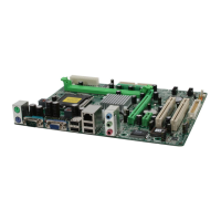
WarpSpeeder Auto-Overclock and Monitoring

Related product manuals