Do you have a question about the Biostar U8638 and is the answer not in the manual?
Overview of the mainboard's design and commitment to reliability and performance.
Details CPU, Speed, Chipset, and DRAM Memory specifications.
Information on the Phoenix BIOS, APM support, USB, and ACPI features.
Lists the included accessories and software with the mainboard.
Details integrated Fast Ethernet MAC, speeds, PCI controller, Wake-On-LAN.
Describes the memory controller providing shadow RAM and ROM BIOS support.
Explains power management features and wake-up capabilities.
Lists the available AGP, CNR, and PCI bus slots on the mainboard.
Notes support for flash memory functionality and ESCD functionality.
Details CRT RGB interface, 2D and 3D graphics acceleration features.
Lists ROP3 Ternary Raster Operation BitBLTS and color depth acceleration.
Explains SMA, frame buffer, triangle setup, and 128-bit 2D graphics engine.
Covers multi-textures, anisotropic filtering, stencil buffer, and texture capabilities.
Details support for four IDE drives, transfer rates, DMA modes, and CD-ROM.
Specifies AC-LINK protocol compliance and 18-bit stereo ADC/DACs.
Lists Parallel, Serial, IrDA, PS/2, and floppy disk connectors.
Describes monitoring of CPU Fan Speed and System Voltage.
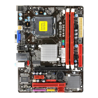
Diagram showing the physical layout of components on the U8638 mainboard.
Index of mainboard components with their locations and labels.
Step-by-step guide for installing a CPU and its fan into Socket 478.
Pin definition and layout for the CPU fan header (JCFAN1).
Pin definition for the system fan header (JSFAN1), including optional status.
Pin definition for the North Bridge chipset fan header (JNFAN1), including optional status.
Configuration options for the CNR codec selection using jumper JCODECSEL.
Pin assignment and function details for the front panel connector (JPANEL1).
Details on connecting an offboard speaker for error beep codes.
Connector for attaching a momentary SPST switch for system reset.
Connector for the front panel power LED indicator.
Connector for the front panel hard drive activity LED indicator.
Connector for infrared sensing devices for data transfer.
Connector for a button to conserve energy by powering down monitor/hard disk.
Connector for the front panel power switch to turn the system on/off.
Pinout and assignment for the 20-pin ATX power connector.
Pinout and assignment for the 12V ATX power connector.
Pinout and assignment for the optional AUX power connector.
Details on the Enhanced PCI IDE controller and IDE connectors (IDE1, IDE2).
Details on the floppy disk connector (FDD1) and supported disk types.
Jumper settings for 5V/5VSB selection for the keyboard connector (JKBV1).
Jumper settings for 5V/5VSB selection for USB ports (JUSBV1).
Pinout for the Wake On LAN header (JWOL1).
Pinouts for the front USB headers (JUSB2 and JUSB3).
Jumper settings for clearing CMOS data and normal operation (JCMOS1).
Details on DRAM type, memory module size, and ECC function disabling.
Instructions for installing DIMM memory modules into the sockets.
Pinout and assignment for the PS/2 mouse and keyboard connector (JKBMS1).
Details on USB and LAN port connectors.
Pinout and assignment for USB connectors.
Details on the optional LAN port connector for internet connectivity.
Explanation of serial and parallel interface ports.
Details on the serial interface port (JCOM1) and its pinout.
Pinout and assignment for the monitor connector (JVGA1).
Details on the parallel interface port (JPRNT1) and its pinout.
Connector for joysticks, game pads, and MIDI devices.
Details on audio output (Speaker Out) and input (Line In, Mic In).
Overview of the mainboard's audio subsystem components.
Pinout for the CD-ROM audio-in header (JCDIN1).
Pinout for the optional CD-ROM audio-in header (JCDIN2).
Pinout for the front panel audio header (JAUDIO1).
Pinout for the telephony audio header (JTAD1).
| Form Factor | Micro ATX |
|---|---|
| Socket Type | Socket 478 |
| Memory Type | DDR SDRAM |
| Max Memory | 2 GB |
| Storage Interface | 2 x SATA |
| Audio | 6-channel AC'97 |
| LAN | 10/100 Mbps |