Do you have a question about the Biostar U8568 and is the answer not in the manual?
Details CPU, speed, chipset, and DRAM memory specifications.
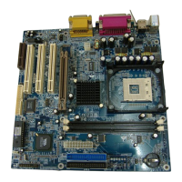
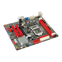
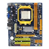
Diagram showing the physical layout of mainboard components and connectors.
Step-by-step guide for installing a CPU into Socket 478.
Diagram showing layout of jumpers and headers for CPU configuration.
Diagram showing the location of various jumpers, headers, and connectors.
Pin assignment and function for the front panel connector.
Pin assignment for the ATX 20-pin power connector.
Pin assignment for the ATX 12V power connector.
Details on IDE connectors for hard disk and CD-ROM drives.
Details DRAM access time and supported memory types for DDR and SDR.
Pinout and signal descriptions for serial interface ports.
Pinout and signal descriptions for the parallel interface port.
| Brand | Biostar |
|---|---|
| Model | U8568 |
| Category | Motherboard |
| Language | English |