12
MAIN DRIVE CHAIN AND SPROCKET LUBRICATION (continued):
Recommended types of chain lubricant are those with Molybdenum Disulphide or Graphite added. Also
bonded lubricants such as Dow Corning Molykote 321R or equivalent are excellent for open chains. The
lubricant should be of a viscosity whereby it will “ow” somewhat and penetrate the internal working
surfaces. Thick stiff greases are of little value because they cannot work into moving parts of the chain.
a. Unplug mixer/grinder from power source and perform lockout/tagout procedures.
b. Remove rear drive cover.
c. Spray or brush lubricant on inside of chain, slowly and carefully turning large sprocket by hand.
d. Reinstall rear drive cover.
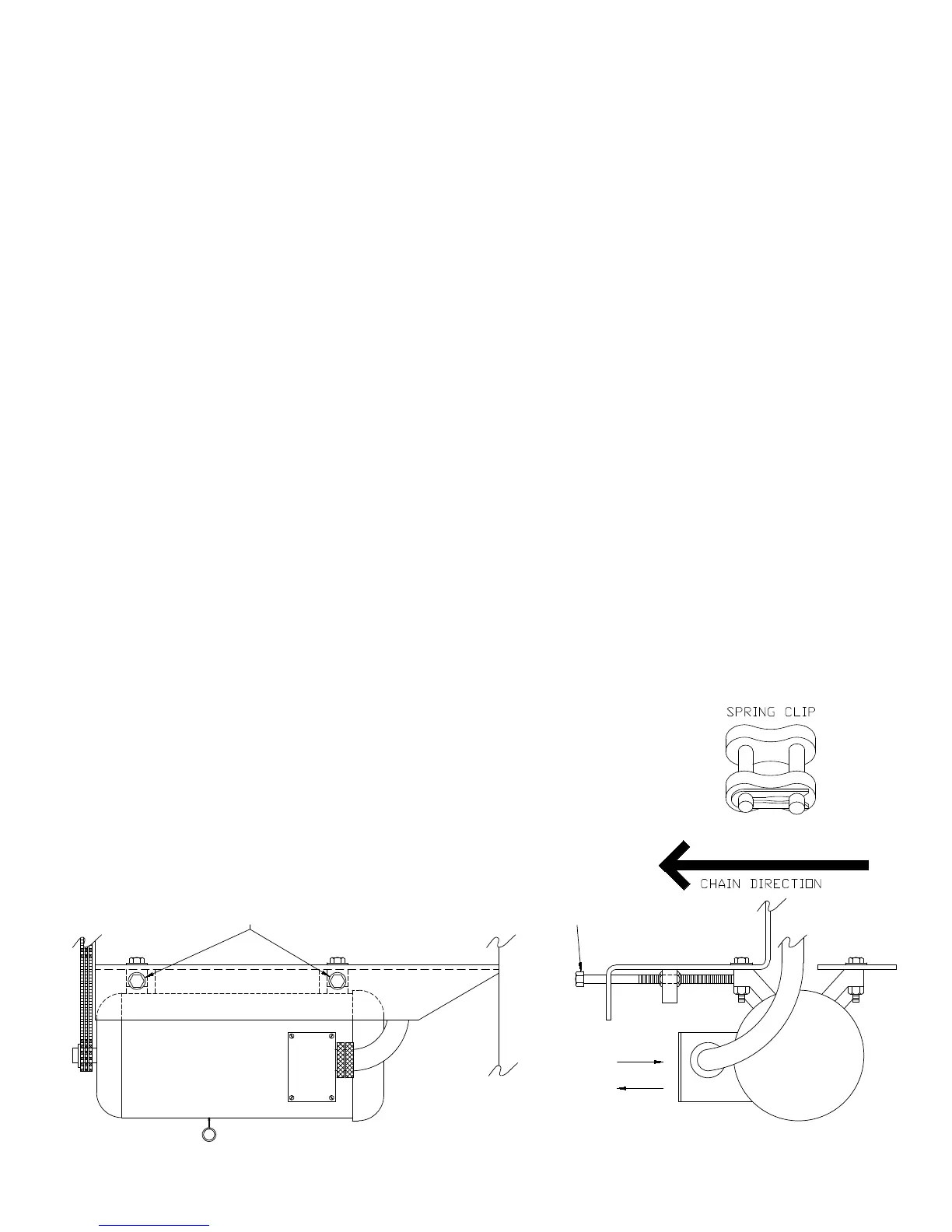
F. MAIN DRIVE CHAIN TENSION ( See Diagram Below)
1. Unplug mixer/grinder from power source and perform lockout/tagout procedures.
2. Remove rear drive cover.
3. Remove right and left side skirts.
4. Loosen the four bolts that hold the motor to the frame of the machine.
5. Loosen the lock nuts on the motor adjusting stud.
6. To Loosen Chain Tension. Turn motor adjusting studs counterclockwise. Grasp motor and pull toward
adjusting stud. Be sure to turn both adjusting studs the same amount and evenly. Total chain ex should
be ⅛ to ⅜”. Be sure to keep motor shaft parallel with auger drive shaft.
To Tighten Chain Tension. Turn motor adjusting studs clockwise. Be sure to turn both adjusting studs
the same amount and evenly. Total chain ex should be ⅛ to ⅜”. Do not over tighten chain as this will put
excessive and damaging pressure on the motor bearings. Be sure to keep motor shaft parallel with auger
drive shaft.
7. Re-tighten motor mounting bolts.
8. Re-tighten motor adjusting stud lock nuts.
9. Reinstall the right and left side skirts.
10. Reinstall the rear drive cover.
G. CHAIN REPLACEMENT
1. Part No. H384-CL Service Replacement Chain is provided with a
“Connecting Link” (Part No. H384-LINK) so that it can be separated
to facilitate installation over the sprockets.
Upon assembly, be sure the connecting link is installed so the spring
clip is orientated with its opening facing “opposite” the direction of
the chain travel (See Diagram at right).
LEFT
MOTOR
TIGHTEN
LOOSEN
HHS100S MOTOR
ADJUSTING STUD
FRONT
ADJUSTING STUDS
HHS100S MOTOR
MOTOR
AFTER INSTALLATION
THE CHAIN SHOULD BE
TENSIONED TO
APPROXIMATELY
⅛ to ⅜ FLEX