Do you have a question about the BIRO Mini-32 and is the answer not in the manual?
Outlines the owner's responsibility for safe operation and the need for trained personnel.
Explains the meaning of warning and caution symbols used in the manual.
Lists critical safety rules and prohibitions for operating the equipment to prevent injury.
Details the necessary conditions for the installation work area and initial machine setup.
Step-by-step guide for removing the machine from its packaging and preparing it for use.
Provides instructions on connecting the machine's electrical supply and required specifications.
Presents a table of motor specifications including HP, KW, VOLTS, HZ, PH, and AMPS.
Explains how to check the auger rotation direction with the auger removed to avoid damage.
Ensures all safety labels are in place and operators are familiar with the manual.
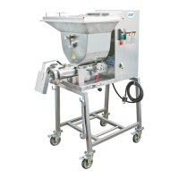
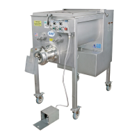
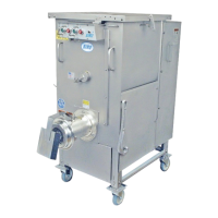
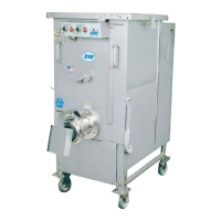
Diagrams and labels identifying the main external parts of the machine.
Shows the function and positioning of the auger engage lever.
Detailed instructions for processing product, including first and second grinds.
Lists essential practices for maintaining knife and plate sharpness and integrity.
Safety precautions before cleaning and step-by-step instructions for cleaning the equipment.
Steps for detaching and reattaching the mixer paddle assembly.
Procedures for removing the hopper and the grinding bowl/auger assembly.
Critical safety measures to observe before performing any maintenance tasks.
Guidelines for lubricating the drive chain, sprockets, and thrust bearing for longevity.
Details on factory fill, oil changing intervals, and specific oil types for gear reducers.
A list of approved lubricants for gear reducers, including manufacturer and product names.
Lists and illustrates the parts associated with the motor drive and hopper covers.
Continues the illustration and listing of parts for the motor drive and hopper covers.
Itemizes the components found within the electrical control box.
Provides a detailed breakdown of parts for the motor-drive unit assembly.
Lists and illustrates the various components of the transmission mounting assembly.
Illustrates and lists the parts that make up the bowl and worm assembly.
Details the specific screws, nuts, and washers used in various machine assemblies.
Wiring diagram for power input, transformer, and primary control circuits.
Details wiring for lid/hopper sensors and transformer connections for various voltages.
Wiring diagrams for safety switches and the hand/foot selector switch.
Wiring details for the electric foot switch, including receptacle and component connections.
Instructions on adjusting the foot switch's internal micro-switches for optimal operation.
Lists the individual components that make up the foot switch assembly.
Diagrams showing where safety and operational labels are affixed to the machine.
Details the text on warning labels and identifies labels for wiring configurations.
A form for operators to sign, confirming they have read and understood the manual.
Specifies what the warranty covers, its duration, and what is excluded.
Outlines the process for obtaining service and registering the product for warranty.
| Model | Mini-32 |
|---|---|
| Category | Grinder |
| Motor Power | 1.5 kW |
| Dimensions | 27 1/4" H x 16 1/2" W x 28" D (69.2 cm H x 41.9 cm W x 71.1 cm D) |
| Weight | 125 lbs (56.7 kg) |
| Construction | Stainless Steel |
| Plate Size | 32 |
| Grinding Capacity | 32 kg/h |
| Voltage | 220-240 V |