6. Manufacturer’s declaration on EMC ·································································· 51
6.1 Electromagnetic emissions ····························································································· 51
6.2 Recommended separation distances between portable and mobile RF communications
equipment and the BT-550 ···························································································· 52
6.3 Electromagnetic immunity ······························································································ 53
7. Technical specifications ···················································································· 55
Product Warranty ·································································································· 57
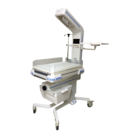
Figure 1-1: Front View ··············································································································· 14
Figure 1-2: Side view ················································································································· 14
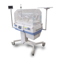
Figure 1-3: System components ································································································ 15
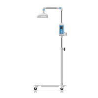
Figure 1-4: Head ························································································································ 16
Figure 1-5: Column ···················································································································· 17
Figure 1-6: Bassinet ··················································································································· 18
Figure 1-7: Stand part ················································································································ 19
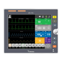
Figure 1-8: Display when SpO
2
option not installed ·································································· 20
Figure 1-9: Display when SpO
2
option installed ········································································· 20
Figure 1-10: Buttons ·················································································································· 21
Figure 1-11: POWER Fail ············································································································· 23
Figure 1-12: Sensor Disable ········································································································ 23
Figure 1-13: S1 Temp Error ········································································································· 23
Figure 1-14: S2 Temp Error ········································································································ 23
Figure 1-15: Baby Check ············································································································· 23
Figure 1-16: Head Rotation ········································································································ 23
Figure 1-17: Masimo Check Alarm ····························································································· 24
Figure 1-18: Masimo Alarm Message ························································································· 24
Figure 2-1: Repositioning the column (1) ·················································································· 27
Figure 2-2: Repositioning the column (2) ·················································································· 28
Figure 2-3: Repositioning the column (3) ·················································································· 29
Figure 2-4: Installing IV pole ······································································································ 30
Figure 2-5: Installing plate for auxiliary equipment ··································································· 31
Figure 2-6: Separating barriers ·································································································· 32
Figure 2-7: Tilting handles ·········································································································· 33
Figure 2-8: Skin temperature sensor ·························································································· 34
Figure 2-9: Power cord ··············································································································· 35
Figure 2-10: Product logo and initial screen··············································································· 35
Figure 2-11: Caster locks ············································································································ 47