KW-210-2 21
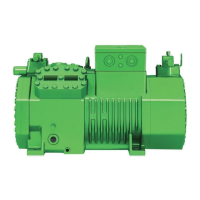
2. Checking whether the device is de-energised
▶ Use a voltage detector and check the phases L1, L2,
L3 and
▶ the terminal strip X102 (if a device is connected to
it).
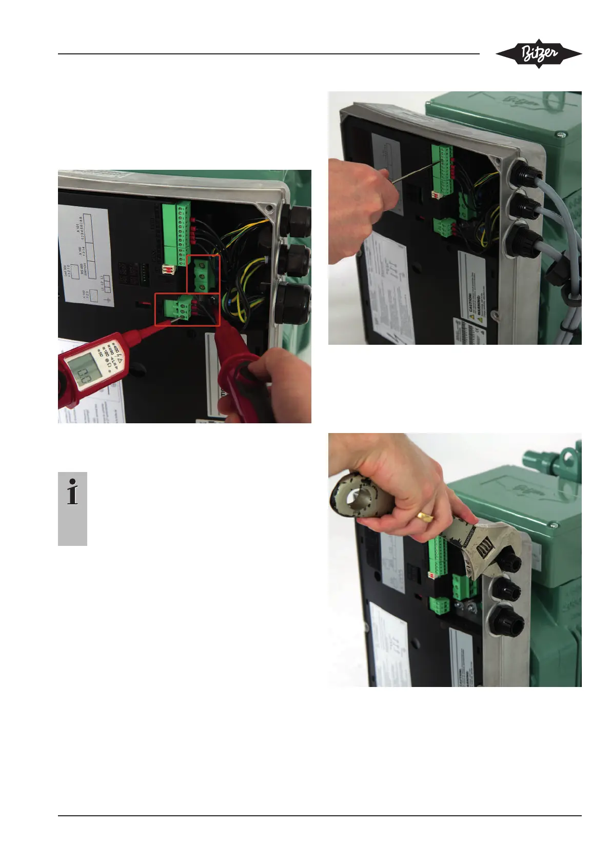
3. Disconnecting the cables at the power and
control connections
Information
The control lines must be connected to the new
frequency inverter in the same way.
Make sure to memorise the wiring or note the
cable positions on the terminal strips using ad-
hesive tape and a marker!
▶ Unscrew the screwed cable glands with the ad-
justable spanner.
▶ Remove the terminals of the power connections L1,
L2, L3 from the terminal screws.
▶ Use a screwdriver (SL2.5x75) to unscrew the termin-
als of the control connections from the terminal strips
X100, X101 and X102.
▶ Remove all cables from the FI housing.
4. Removing the screwed cable glands from the FI
▶ Use an adjustable spanner to completely dismount
the two upper M20 screwed cable glands and store
them. They are needed again for mounting the new
frequency inverter (FI).

 Loading...