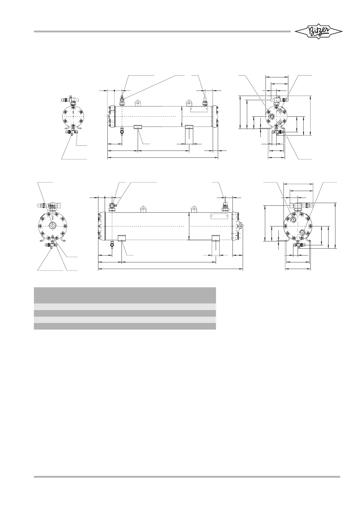
Maßzeichnungen
OW401 & OW501
OW781 & OW941
Anschluss-Positionen
1 Öl-Eintritt
2 Öl-Austritt
3 Kühlmedium-Eintritt
3a: 4- oder 6Pass
3b: 2- oder 3Pass
4 Kühlmedium-Austritt
4a: 4- oder 6Pass
4b: 2- oder 3Pass
5 Kühlmedium-Ablass
6 Manometer-Anschluss
7–
8–
9 Ölablass
Seewasser beständige Ölkühler auf
Anfrage.
Dimensional drawings
Connection positions
1 Oil inlet
2 Oil outlet
3 Cooling agent inlet
3a: 4 or 6 pass
3b: 2 or 3 pass
4 Cooling agent outlet
4a: 4 or 6 pass
4b: 2 or 3 pass
5 Cooling agent drain
6 Pressure gauge connection
7–
8–
9 Oil drain
Seawater resistant oil coolers upon
request.
Croquis cotés
Position des raccords
1 Entrée d'huile
2 Sortie d'huile
3 Entrée de fluide caloporteur
3a: 4 ou 6 pass
3b: 2 ou 3 pass
4 Sortie de fluide caloporteur
4a: 4 ou 6 pass
4b: 2 ou 3 pass
5 Vidange de fluide caloporteur
6 Raccord du manomètre
7–
8–
9 Vidange d'huile
Refroidisseurs d'huile en version marine
sur demande.
91SH-100-3
12AEE1HL
mm mm mm mm mm mm mm
OW401 22 (7/8'') 22 (7/8'') 863 134 42 400 238
OW501 22 (7/8'') 22 (7/8'') 1113 134 42 740 193
OW741 28 (1 1/8'') 28 (1 1/8'') 889 176 57 400 231
OW941 35 (1 3/8'') 35 (1 3/8'') 1139 182 63 740 186