DB-200-510
T O P
I N
O U T
2
5
7 / 1 6 " - 2 0 U N F
6
7 / 1 6 " - 2 0 U N F
6
1
3 a / 3 b1 0
4 a / 3 b
4 b
9 1 0
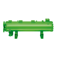
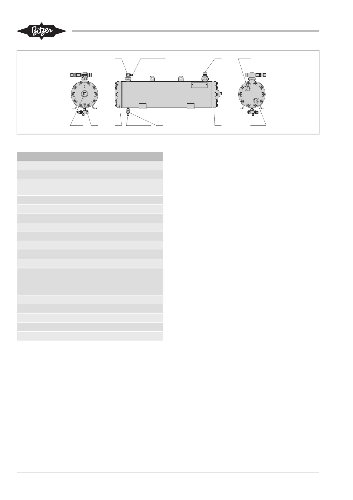
Fig.5: OW401(B) .. OW941(B)
Connection positions
1 Refrigerant or oil inlet
2 Refrigerant or oil outlet
2a Alternative refrigerant outlet (only for sea
water version)
3 Coolant inlet
3a 4 or 6 pass
3b 2 or 3 pass
4 Coolant outlet
4a 4 or 6 pass
4b 2 or 3 pass
5 Coolant drain
6 Connection for pressure gauge
7 Connection for pressure relief valve
Internal thread 3/8-18 NPTF, external
thread 1 1/4-12 UNF
8 Sight glass
9 Oil drain
10 End cover, removable
11 Fixing rail, bottom
12 Fixing rail, top
Tab.4: Connection positions
Dimensions (if specified) may have tolerances accord-
ing to ENISO13920-B.
The legend applies to all water-cooled BITZER con-
densers and oil coolers and contains connection posi-
tions that do not occur in every series.