DB-200-5 23
T O P
I N
O U T
2
5
7 / 1 6 " - 2 0 U N F
6
7 / 1 6 " - 2 0 U N F
6
1
3 a / 3 b1 0
4 a / 3 b
4 b
9 1 0
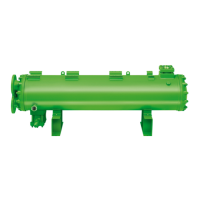
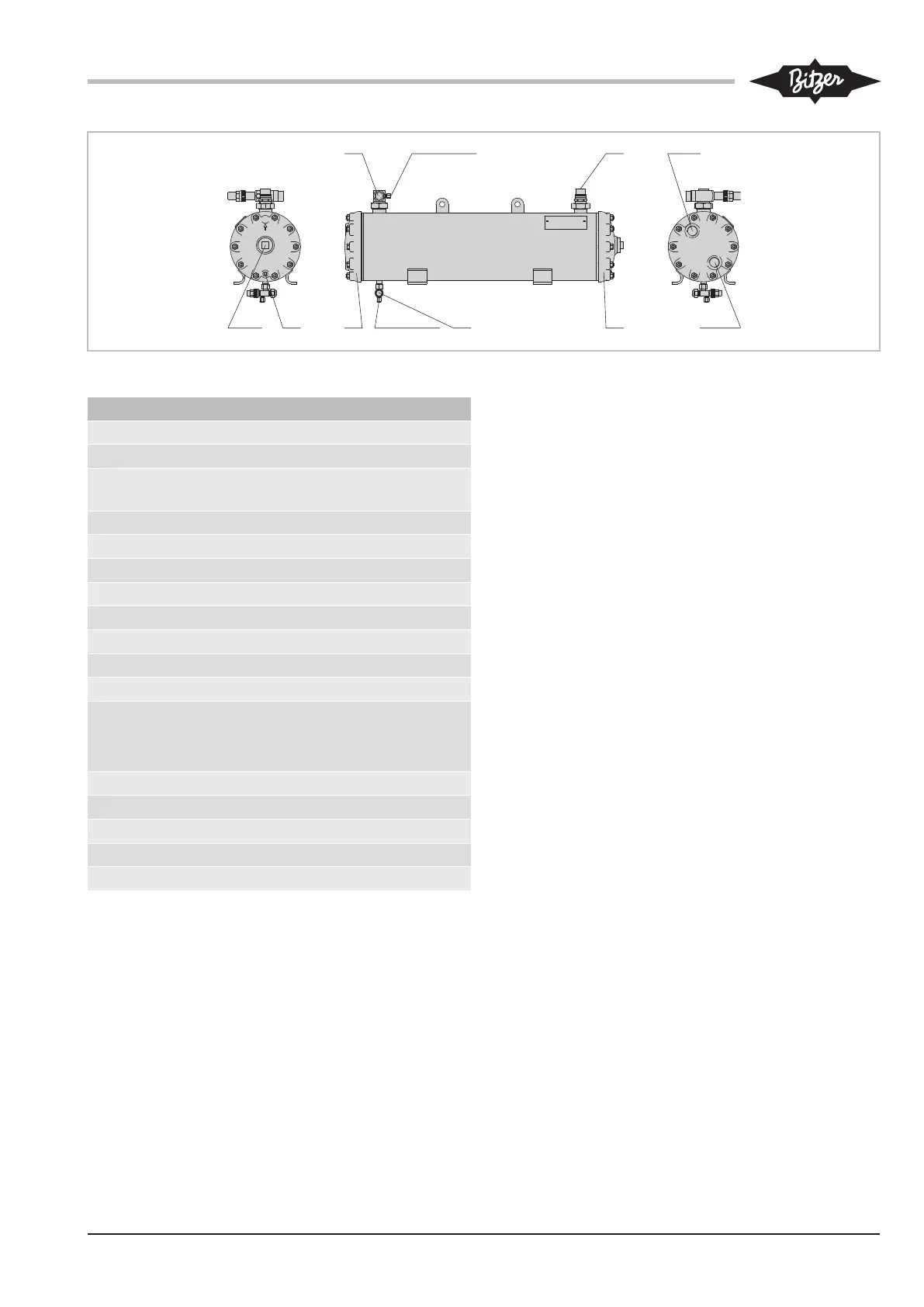
Abb.5: OW401(B) .. OW941(B)
Anschlusspositionen
1 Kältemittel- bzw. Öleintritt
2 Kältemittel- bzw. Ölaustritt
2a Alternativer Kältemittelaustritt (nur bei See-
wasserausführung)
3 Kühlmediumeintritt
3a 4 oder 6 pass
3b 2 oder 3 pass
4 Kühlmediumaustritt
4a 4 oder 6 pass
4b 2 oder 3 pass
5 Kühlmediumablass
6 Anschluss für Manometer
7 Anschluss für Druckentlastungsventil
Innengewinde 3/8-18 NPTF, Außengewin-
de 1 1/4-12 UNF
8 Schauglas
9 Ölablass
10 Umlenkdeckel, abnehmbar
11 Untere Befestigungsschiene
12 Obere Befestigungsschiene
Tab.4: Anschlusspositionen
Maßangaben (falls angegeben) können Toleranzen
entsprechend ENISO13920-B aufweisen.
Legende gilt für alle Wwssergekühlten Verflüssiger und
Ölkühler vonBITZER und enthält Anschlusspositionen,
die nicht in jeder Serie vorkommen.