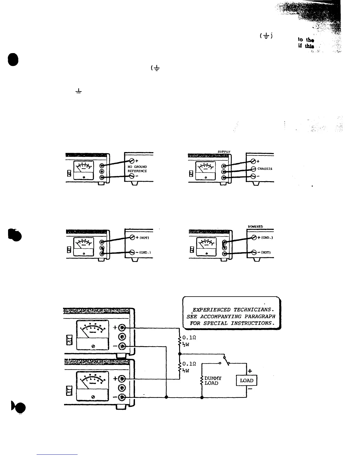
ure 2 shows a typical example. The power supply
offers overload protection; therefore, any fuse in the
equipment’s power cable is not required during
testing. In fact, a convenient connection point may
be to the fuseholder. Normally, the equipment chas-
sis should be grounded. Usually, the negative po-
larity of the equipment is common with the chassis
and a jumper may be connected between the
(*
)
and
(-)
terminals of the power supply.
In those cases where the chassis is not common
with the negative polarity, connect a separate test
lead free from the
(
-h-
)
terminal of the power supply
to the chassis of the equipment being serviced.
Figure 3 shows the proper interconnection between
the power supply and the equipment under test for
all possible situations.
8
POWER
SUPPLY
EQUIPMENT
BEING
POWERED
EQUPMENT
POWER
BEING
SUPPLY
POWERED
-F'
If there is any doubt that the chassis
may
not
be
common with the negative polarity, use a se-
ground connection from the
(*l
terminal
equipment chassis. No damage can result
technique is used.
Set the power supply voltage to the specification
voltage for the equipment being serviced
(normally
the voltage value of a fully charged vehicle
battery).
Set the current limit to the maximum input
current
specification plus 5%.
If specification information
is unavailable, start with a moderate current
limit
and find the overload threshold. Increase the
cur-
rent limit 5% above threshold to prevent
overload
turn-off during testing.
Note that most solid
state
receivers have a much higher load current
with
strong audio output. Therefore, the threshold
should
EQUIPMENT
POWER
BEING
POWERED
POWER
EQUIPMENT
BEING
SUPPLY
Figure 3. Power Supply Interconnect Possibilities
POWER SUPPLY
#l
f
RECOMMENDED ONLY FOR
POWER SUPPLY
#2
Figure 4. TWO Power Supplies Connected in Parallel for 4 Amp Output