CIRCUU
IT DESCRIPTION
GENERAL
The power supply converts a 117 VAC input to a
highly regulated and filtered dc output that is fully
adjustable from 0 to 50 volts and 0 to 2 amperes.
The circuits that accomplish this action may be
divided into five main groups as follows:
-Unregulated B+ Source. Converts the ac input
into a raw, unregulated dc voltage.
_V+
and V- Source.
Converts the ac input to
+15
VDC (V+) and -15 VDC
(V-)
for powering
active elements ICI and IC2 in the control circuits
and control sensing circuits group.
-Control Circuits.
Controls the unregulated B+
source to provide a highly regulated B+ output
that is adjustable from 0 to 50 volts.
-Current
Sensing Circuits. Establishes the current
limit, senses the load current, and activates
an
overload detector that shuts down the power
supply if the current limit is exceeded.
-Metering. Monitors the output voltage and
current.
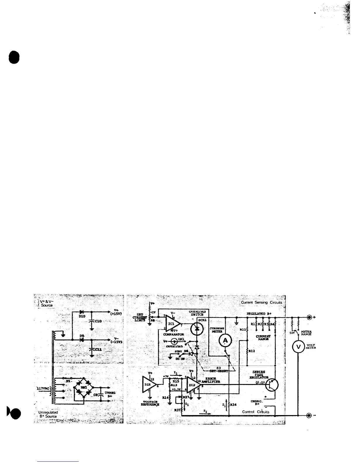
Refer to Figure 9, the functional diagram, and to
the schematic diagram. Circuit descriptions make
constant reference to these diagrams.
NOTE
The voltages in the following circuit de-
scriptions, and on the diagrams, are meas-
ured with respect to the regulated B+
output (the + terminal). Note that this
point is floating independent of the chassis
of the power supply.
UNREGULATED B+ SOURCE
The unregulated B+ source circuit converts the
117 volt ac input to a raw, unregulated B+ output.
Later,
in the control circuits, the unregulated B+ is
converted into the regulated B+ output of the power
supply.
The unregulated B+ output level is
pre-regulated
in coarse steps. As the LEVEL control is rotated
clockwise from zero to maximum, the unregulated
B+ voltage changes from its lowest to its
highest
value in four steps.
This minimizes the
difference
between the unregulated B+ and the regulated B+
output, which always keeps power dissipation
with-
in safe limits.
The main components which make up
this
circuit
are power transformer
Tl,
pre-regulator switch
as-
sembly S5, bridge rectifier
BRl,
and filter capacitor
C8.
The ac input is applied to the unregulated
B+
circuit through on-off switch S4 (which is
part
of the
LEVEL control), across neon POWER lamp
NE1
(which glows continuously as a pilot lamp to
show
that power is on), to power transformer
Tl.
Power
transformer
Tl
has four taps in its
main
power out-
put winding. At the lowest voltage setting, only the
low voltage portion of the
transformer
is connected
into the rectifier (this is the condition shown on the
schematic diagram). As the LEVEL control is rotated
clockwise, cams operate microswitches
S5-C,
then
S5-B,
and finally
S5-A.
Each cam-operated
micro-
switch selects another tap on the secondary of the
power transformer and sequentially steps the rec-
tifier input voltage to a higher value.
Bridge rectifier BRl converts the ac power to full
wave dc, which is filtered by C8. The unregulated
B+ output at C8 is regulated and filtered by the
control circuits.
V+ AND V- SOURCE
The V+ and V- source is a completely separate
power source for powering comparator
IC1.
and
voltage reference and error amplifier
IC2.
These
circuits must be free from the extreme voltage
var-
iations found in the other power source circuits.
Figure 9. Power Supply Functional Diagram
12