the power supply is not normally used nor required
in this application.
Using separate test lead colors,
such
as red and black, reduces the chance of acci-
dental
reverse polarity connection. Set the current
limit to the maximum input current specification of
the equipment being serviced.
If
this figure is un-
kn
o
wn, start with a low current limit and increase
the setting in small increments until the overload
circuit in the power supply does not trip when power
is applied to the unit under test. Set the voltage to
the same value that would be present if a full set of
fully charged batteries were installed. Flashlight
cells of all sizes are rated at 1.5 volts ‘each. Other
batteries normally state the voltage on the label,
and
the required operating voltage for the equip
ment being serviced is often stated on a label in
the equipment. For units using more than one bat-
tery, check whether the batteries are connected in
series or parallel. For the parallel connected ar-
rangement, set the power supply voltage to that of
a single cell; a higher voltage may damage the
equipment. For the series connected arrangement,
add the voltages of all cells and set the power sup
ply voltage to that sum.
A simplified method of making connections to the
power input points of battery operated equipment
may be to use a “dummy” battery. A dummy bat-
tery sits in the battery compartment and makes
good electrical contacts with the power input points,
but has readily accessible terminals or test leads
for interconnection to the power supply. The body
of the dummy battery may be made from wood or
other nonconductive material. The end caps must
be good electrical conductors which are connected
to terminals or test leads. The unit must fig snugly
in the battery compartment to assure good electrical
contact. An improved version may include a spring
to insure a snug fit.
SERVICING VEHICULAR
ELECTRONICS EQUIPMENT
When servicing electronics equipment for auto.
mobiles. trucks, and other vehicles, the equipment
is normally removed from the vehicle for bench
testing.
This power supply is an excellent dc power
source for bench testing such equipment. The
fol-
lowing items are among the more common types of
vehicular electronics equipment that may be
powered from this power supply:
POWER
SUPPLY
AM, AM/FM and AM/FM/Stereo automobile
receivers
*Tape players
Citizen’s band transceivers
Monitor receivers
Automobile amateur radio receivers
*Some aircraft equipment
*Some ship-to-shore and ship-to-ship marine band
transceivers
*Some vehicular two-way communications trans-
ceivers
*Some automotive amateur radio transceivers
‘Maximum current 2 amperes unless special procedures are
used as described in this section of the
manual.
Most automobiles and other vehicles use
12-volt
electrical systems. Although the electrical system is
normally referred to as a
12-volt
system, actual bat-
tery voltage when fully charged is approximately
14 volts. The power supply may be set
at
14 volts
for servicing equipment from vehicles with
12-volt
electrical systems.
Some trucks use a 24-volt
elec-
trical
system; bench testing of equipment from these
systems should be performed at 28 volts. Aircraft
normally use a 28-volt electrical system, and a
bench test voltaqe of 32 volts is used.
Practically all vehicles use a negative ground
electrical system, althouqh a positive ground system
is occasionally found. Electronic equipment which
is built for use only in negative ground vehicles
usually has its chassis common with the negative
polarity of input power. In some cases, there is no
separate negative polarity power cable, since the
chassis
becomes
grounded
when the equipment is
installed in the vehicle. Some equipment is built for
use in either neqative or positive ground electrical
systems, in which case the chassis may be isolated
from both the positive and ‘negative input polarities.
There is virtually no equipment built for positive
ground electrical systems only, although some elec-
tronics equipment may use its ungrounded positive
polarity as reference for circuit operation.
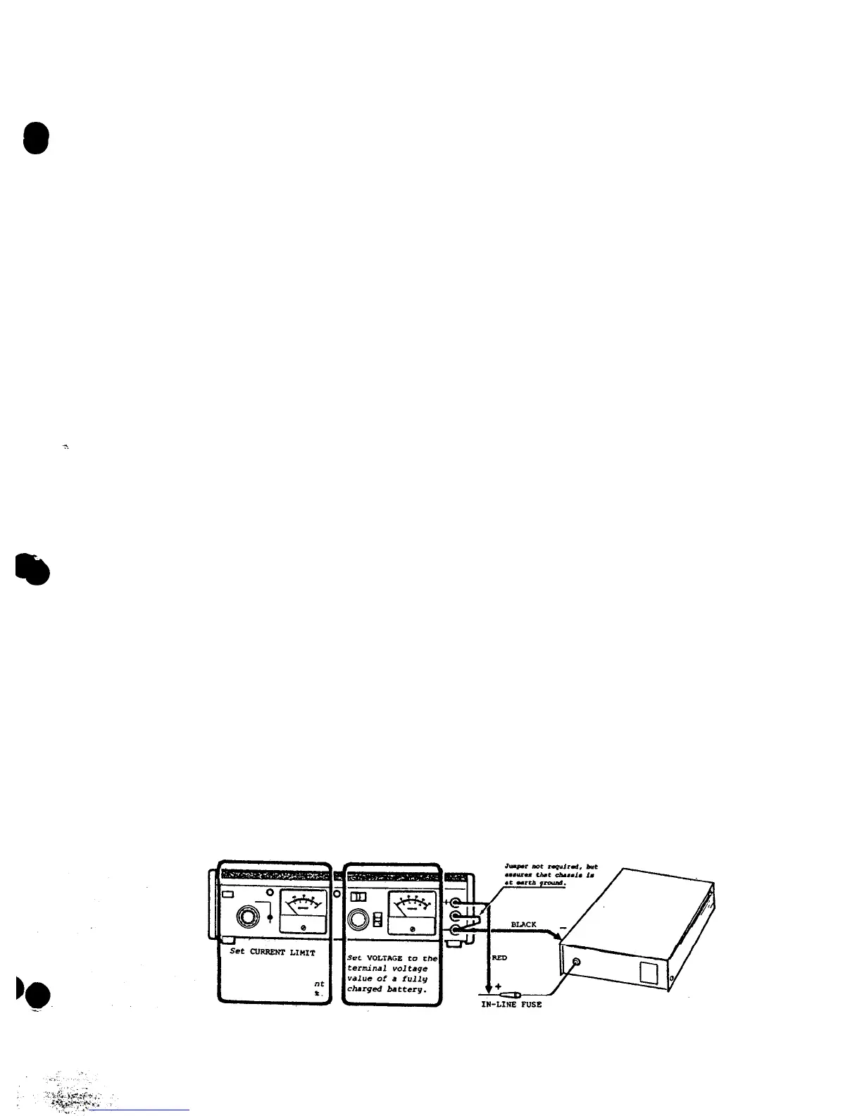
CAUTION
Carefully observe polarity of connections.
Equipment may be damaged if polarities
are reversed.
When servicing this type of equipment, the
(+)
and
(-)
terminals of the power supply should be
connected to the
(+)
and
(-)
power input points of
the equipment being serviced with test leads.
Fig-
EQUIPMENT
BEING
SERVICED
to
maximum
input
current
specifi-
cation of
eguipme
being
serviced
+5
Figure 2. Typical Power Supply Connections to Vehicular Equipment
(Negative Ground System, Grounded Chassis Shown]
7