MAINTENANCE AND CALIBRATION
WARNING
-
THE FOLLOWING INSTRUCTIONS ARE FOR USE BY
QUALIFIED PERSONNEL ONLY. TO AVOID ELECTRICAL SHOCK, DO NOT
PERFORM ANY SERVICING OTHER THAN THAT CONTAINED IN THE OPER-
ATING INSTRUCTIONS UNLESS YOU ARE QUALIFIED TO DO SO.
This power supply is built to provide long,
trouble-free service and does not require periodic
maintenance. If the unit malfunctions, use conven-
tional troubleshooting techniques, such as voltage
and resistors checks, to isolate the defective com-
ponent. If electrical components are replaced, the
unit should be recalibrated.
CALIBRATION
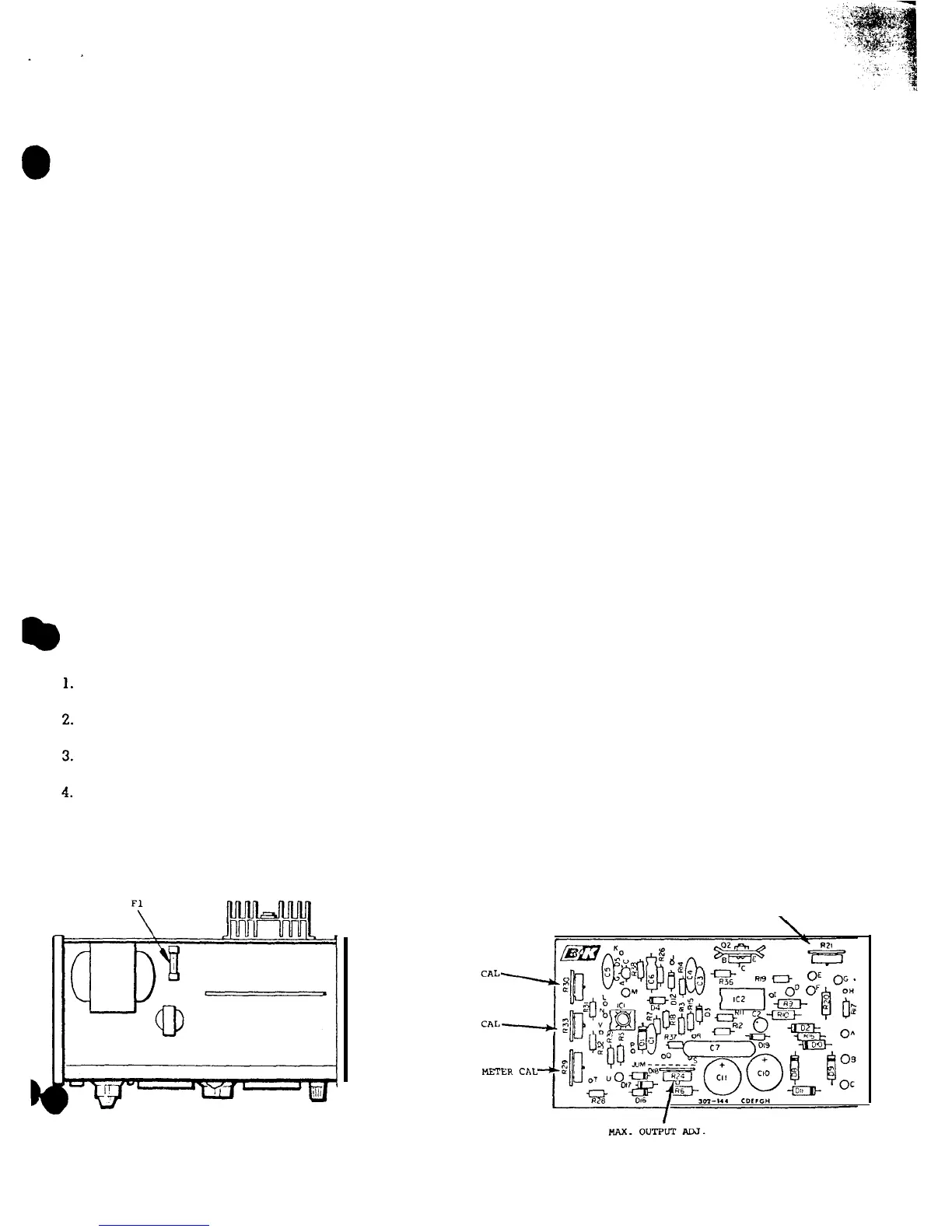
To gain access to the calibration adjustments, re-
move the 3 screws at the rear of the top cover, then
lift the top cover at the rear and slide the front lip
of the cover from the retaining bosses on the front
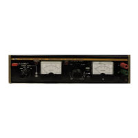
panel. Refer to Figure
10
for locations of calibration
adjustments.
MAX OUTPUT ADJ
(R24)
1. Connect an accurate, calibrated voltmeter to the
output terminals of the power supply.
2. Set the LEVEL control of the power supply to
maximum.
3. Adjust the MAX OUTPUT ADJ potentiometer
(R24)
for exactly 50.5 volts on the external volt-
meter.
25V CAL
(R33)
Connect an accurate, calibrated voltmeter to the
output terminals of the power supply.
Set the METER RANGE switch of the power sup-
ply to the 25V position.
Adjust the LEVEL control of the power supply for
exactly 20 volts on the external voltmeter.
Adjust 25V CAL potentiometer
(R33)
for exactly
20 volts on the voltmeter of the power supply.
50 VOLT
25 VOLT
CURRENT
5OV
CAL
(R30)
1.
2.
3.
4.
Connect an accurate, calibrated voltmeter to the
output terminals of the power supply.
Set the METER RANGE switch of the power
sup-
ply to the
5OV
position,
Adjust the LEVEL control of the power supply for
exactly 50 volts on the external voltmeter.
Adjust
5OV
CAL potentiometer
(R30)
for exactly
50
volts on
the voltmeter of the power supply.
CURRENT
METER CAL (R-29)
1. Connect an accurate, calibrated ammeter ca-
pable of 2A in series with an appropriate load
(1 ohm, 4 watts) to the output terminals of the
power supply.
2. Adjust the LEVEL control of the power supply
for exactly 2A on the external ammeter.
3. Adjust CURRENT METER CAL potentiometer
(R29)
for exactly 2A on the current meter of the
power supply.
INTERNAL CURRENT LIMIT ADJ. (R-21)
1. Turn SET CURRENT LIMIT (3) to full C.W.
2. Adjust R-21 to full scale when pressing the set/
reset button (4).
FUSE REPLACEMENT
If these is no power supply output and the
POWER lamp does not light, check fuse
Fl.
The
fuse
Fl
is located inside the cabinet, which is made
accessible by removing the 3 screws at the rear of
the top cover, then lifting the top cover at the rear
to slide the front lip of the cover from the retaining
bosses on the front panel.
Fuse
Fl
is soldered to a terminal strip at the right
of the main power transformer. Figure 10 shows the
location of the fuse.
INTERNAL CURRENT LIMIT ADJ
\
-ERChL
14
Figure
10.
Location of Calibration Adjustments and Fuses