33
Appendix B: RS-232 Pinouts
B.1 Pinout on DB25 (IC470A through IC472A Models)
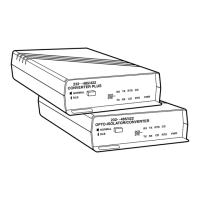
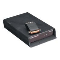
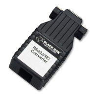
The IC470A, IC471A, and IC472A models of the
Converter have a standard RS-232 interface pinned out,
as shown on the next page, on a DB25 female (pictured)
or male connector.
When the Converter is set as DTE, it transmits data to
the attached RS-232 device on Pin 2 (Transmit Data,
TD) and receives data from that device on Pin 3
(Receive Data, RD). When the Converter is set as DCE, it
receives data on Pin 2 and transmits on Pin 3.
Two sets of RS-232 control signals, RTS/CTS and
DTR/DSR/CD, are jumpered together inside the
Converter. If the Converter receives Request to Send
(RTS) on Pin 4, the Converter loops it back on the Clear
to Send line (CTS, Pin 5), and vice versa. If the
Converter receives a control signal on either Data
Terminal Ready (DTR, Pin 20), Data Set Ready (DSR,
Pin 6), or Carrier Detect (CD, Pin 8), the Converter
loops it back to any of these three lines on which it is not
receiving a signal.
APPENDIX B: RS-232 Pinouts
 Loading...