4
1. 8 7 7. 8 7 7. 2 2 6 9 BLACKBOX.COM
NEED HELP?
LEAVE THE TECH TO US
LIVE 24/7
TECHNICAL
SUPPORT
1.877.877.2269
CHAPTER 1: OVERVIEW
1.3 HARDWARE DESCRIPTION
1.3.1 FRONT PANEL OF THE SWITCH
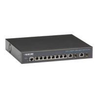
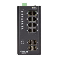
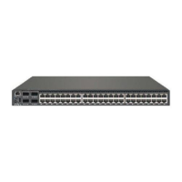
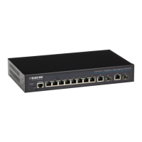
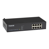
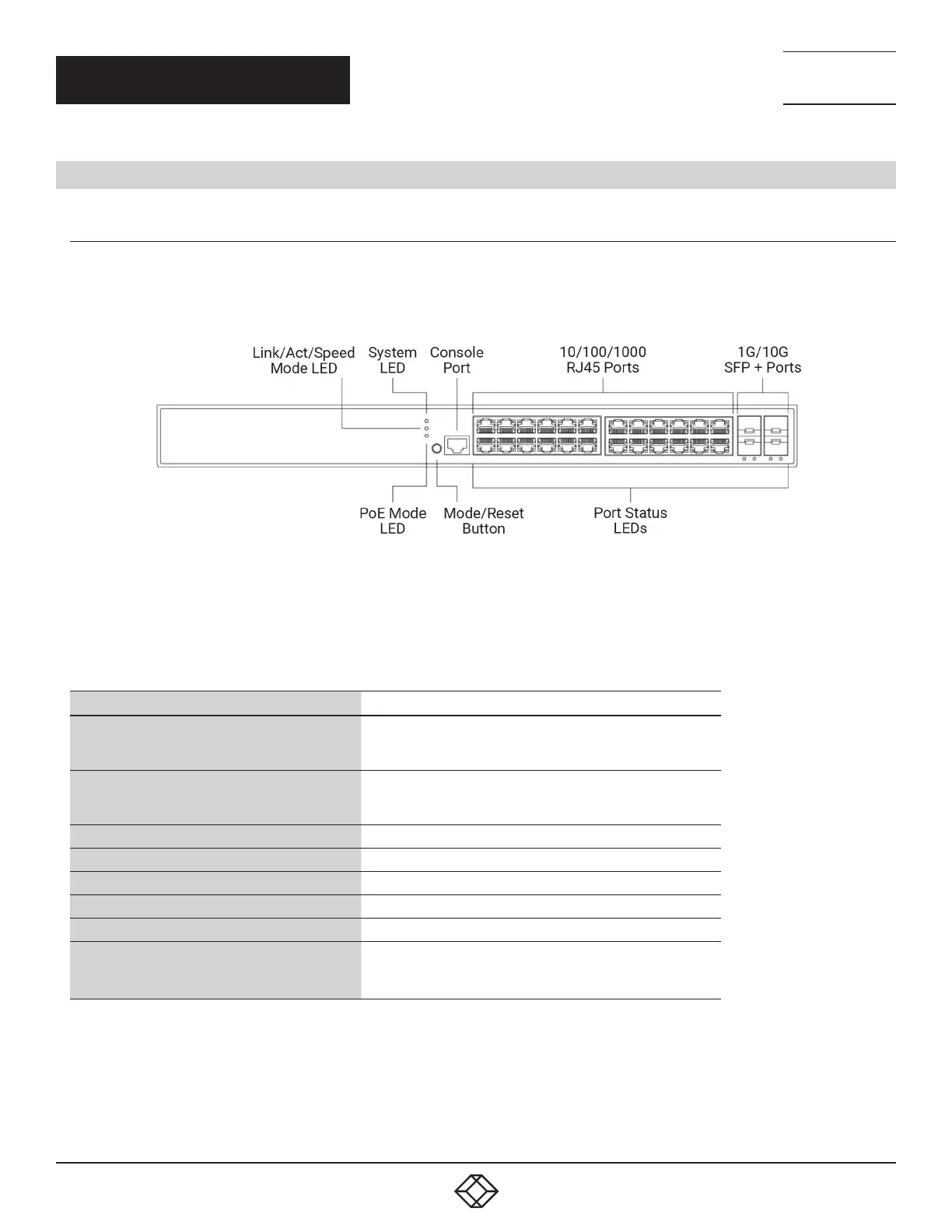
Figure 1-1 shows the front panel of the switch. Table 1-1 describes its components.
FIGURE 1-1. FRONT PANEL OF THE SWITCH
NOTE: The 28-port switch is shown. The 10- and 52-port switches are similar, but have a different number of ports.
TABLE 1-1. FRONT-PANEL SWITCH COMPONENTS
COMPONENT DESCRIPTION
(1) Link/Act/Speed Mode LED
Indicates the mode of all ports on the switch. Users can
press the Mode button sequentially to switch among the two
different modes (Link/Activity/Speed mode and PoE mode).
(1) System LED
Indicates if the switch is powered up correctly or not,
or, indicates if there is a system alarm triggered for
troubleshooting.
(1) Console port Links to RS-232 console for management
(8), (24), or (48) 10/100/1000 RJ-45 ports Connect to twisted-pair devices
(2) or (4) 1G/10G SFP+ Ports Connect to 1G/10G fiber uplinks
(1) PoE Mode LED Lights when the port is using Power over Ethernet (PoE)
(1) Mode/Reset button Press to select the mode, or to reset the switch
(10), (28), or (52) Port Status LEDs
Indicates the current status of each port. Users can check
these LEDs to understand the port status in different modes,
after changing the mode by pressing the Mode button.