6.
7.
8.
9.
Connect the black (power ground) lead to a grounded metal part on the vehicle. We recommend
grounding all audio system black ground leads (receiver, changer,-additional amplifiers, etc.) to
a common grounding point, preferably a non-painted surface under the instrument panel.
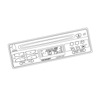
Fig. 4
Connect the yellow (constant power) input lead to a source of constant battery power, preferably
directly to the battery. The wire must be
18-gauge
or thicker.
After the other leads are connected, connect the red turn-on “IGNITION” lead using either of the
following alternatives:
A.
B.
(Recommended)
-
Connect it to a positive (+) 12 Volt power terminal that is energized only
when the ignition key is set to the “on” position or accessory position. (You can still turn the
unit on for one hour even if the ignition is off.)
This lead can instead be connected to a source of constant power, however, your receiver’s
operation will be completely separate from the ignition.
With either alternative, the receiver’s DSC Setting
“DISP
ON/OFF” allows you to choose whether
or not the receiver and its display are illuminated when the receiver is turned off, but still receiving
power via the red lead.
Cover the ends of any unused leads with electrical tape. This will prevent them from touching the
vehicle or each other and causing a short circuit and damage to the receiver or vehicle.
1 O.Reconnect the vehicle’s battery.
11
.Verify
that no fuses have blown.
B.
1.
2.
3.
4.
5.
6.
.
Test the Connections
To help prevent possible electrical damage from accidental
misconnection
of the receiver, first
attach your vehicle’s antenna. (With Florida RD 168, Nevada RDM 168 and Alaska RDM 168
only: if necessary, attach the antenna “elbow” connector and affixing bracket to the back of the
receiver.)
Be sure to detach the faceplate before you start to connect the receiver.
Plug the harness into the receiver.
Verify that the receiver’s and vehicle’s fuses haven’t blown.
Attach the faceplate and test the receiver.
Once the connections have been successfully made, you can begin the INSTALLATION. (See
below.)
GB2
 Loading...