- 2 -
D
Inhaltsverzeichnis
Belegung des Anschlußkästchens ........................................ 2
Meßpunkte und Abgleichelemente ....................................... 3
Demontage ........................................................................... 4
Elektrischer Abgleich ............................................................ 5
Antennenanpassung ............................................................. 6
Testmode .............................................................................. 7
Servicemode ......................................................................... 8
FM-Abgleich .......................................................................... 8
Programmierung der FM-Feldstärkespannung ..................... 9
Programmierung der AM-Feldstärkespannung ..................... 10
F
Table des matières
Configuration de broches du bloc de connexion ................... 11
Points de mesure et éléments de réglage ............................ 3
Démontage ........................................................................... 12
Réglage électrique ................................................................13
Adaptation de l‘antenne ........................................................ 14
Mode de test ......................................................................... 15
Mode de service....................................................................16
Réglage FM .......................................................................... 16
Programmation de tension de l'intensité de champ FM .......17
Programmation de tension de l'intensité de champ AM ........ 18
D
Belegung des Anschlußkästchens
GB
Table of Contents
Pin assignment of the quick-fit connector ..................................... 2
Measuring points and alignment elements ................................... 3
Disassembly.................................................................................. 4
Electrical alignment ....................................................................... 5
Antenna matching ......................................................................... 6
Test mode ..................................................................................... 7
Service mode ................................................................................ 8
FM alignment ................................................................................ 8
Programming of the FM field-strength level .................................. 9
Programming of the AM field-strength level ................................ 10
E
Tabla de materias
Disposición de conectadores de la caja de conexión ................... 11
Puntos de medición y elementos de alineamiento........................ 3
Desmontaje ................................................................................. 12
Alineamiento eléctrico ................................................................. 13
Adaptación de la antena ............................................................. 14
Modo de test ............................................................................... 15
Modo de servicio ......................................................................... 16
Alineamiento FM ......................................................................... 16
Programación de tensión de la intensidad de campo FM ........... 17
Programación de tensión de la intensidad de campo AM........... 18
GB
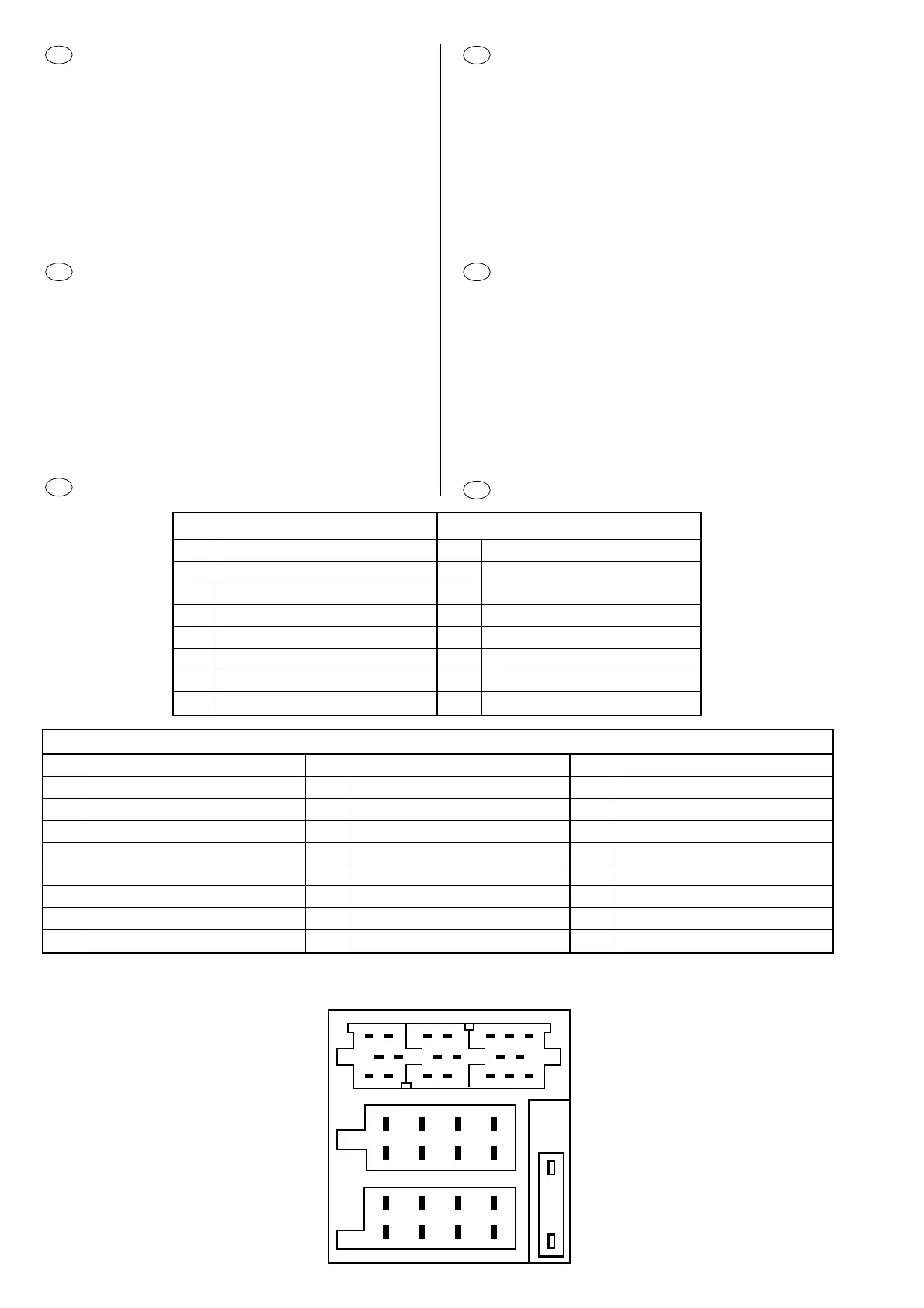
Pin assignment of quick-fit connector
1
2
3
4
5
6
7
8
1
2
3
4
5
6
7
8
C
B
A
14
7
10 13
16
19
3
6
9
12
15
18
2
58
11
14 17
20
C-1 C-2 C-3
C
C1 C2 C3
1 Line out LR 7 NC 13 NC
2 Line out RR 8 NC 14 NC
3 Line out Masse / Line out Ground 9 NC 15 NC
4 Line out LF 10 FB + 12V / RC + 12V 16 NC
5 Line out RF 11 Fernbedienung / Remote Control 17 NC
6 +12 V (Verstärker) / +12 V (Amplifier) 12 FB - Masse / RC - Gnd 18 NC
19 NC
20 NC
BA
1 Lautspr. / Speaker Out (RR) + 1 NC
2 Lautspr. / Speaker Out (RR) - 2 Telefon Mute / telephone mute
3 Lautspr. / Speaker Out (RF) + 3 NC
4 Lautspr. / Speaker Out (RF) - 4 Dauerplus / Permanent plus (KL 30)
5 Lautspr. / Speaker Out (LF) + 5 Automatik-Antenne / Automatic antenna
6 Lautspr. / Speaker Out (LF) - 6 Beleuchtung / Illumination
7 Lautspr. / Speaker Out (LR) + 7 Zündungsplus / Ignition plus (KL 15)
8 Lautspr. / Speaker Out (LR) - 8 Masse / Ground
 Loading...