Lit. No. B64118, Rev. 03 17 March 1, 2009
6. Remove the bottom bolt, lock washer and fl at
washer from the rear pump mount bracket. Route
the black ground wire (from the harness) under the
pump on the driver's side of the A-frame. Align the
tooth lock washer and end ring terminal over the
hole on the bracket and secure them with the lock
washer and bolt.
NOTE: A medium strength thread-locking
compound should be used on all of the pump
mount fasteners.
7. Secure the manifold to the A-frame. Remove
the washers, lock washers and cap screws from
the manifold and align the mount holes with the
A-frame brackets. Properly replace and tighten all
hardware. The passenger-side mount bracket is
the ground for the manifold coil harness.
NOTE: A medium strength thread-locking
compound should be used to secure the manifold
mount fasteners.
8. The manifold contains a red coil wire harness
that must be grounded to the A-frame. Secure
the 3/8" end ring terminal from this harness
to the passenger-side manifold mount bracket
with existing manifold mount hardware. The
internal/external tooth lock washer provided
should install against the mount bracket to provide
a solid ground.
MANIFOLD ASSEMBLY & ELECTRICAL INSTALLATION – SNOWPLOW SIDE
Apply
Thread-Locking
Compound
9. Connect the hydraulic hoses to their respective
adapters on the manifold. Hose PN B60293
Port #3, Hose PN B60432 Port #4 and Hose
PN B60426 Ports #2 and #1. Tighten hoses
according to the torque chart.
10. Position the harness braid in the notch on the
switch bracket and secure it with a cable tie.
NOTE: The diode loop harness should be inside of
the pump cover.
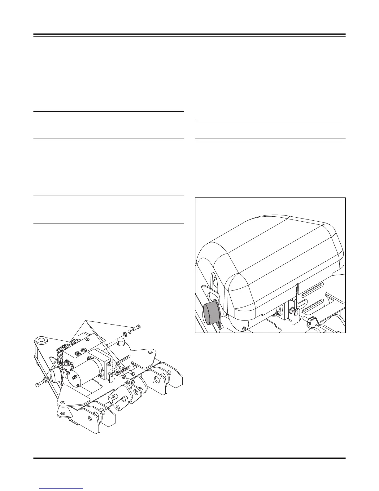
11. Place the power connector, from the harness,
through the hole in the pump and manifold cover.
Position the cover over the protective toggle switch
hood. Align the front and rear holes in the cover
with the U-nuts located on the mount tabs. Secure
the pump cover with two 3/8" x 1-1/8" knobs.
The pump cover installs over the top of the draw
latch switch bracket.