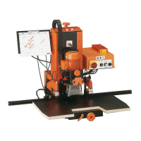
This document describes the Blum PRO-CENTER 2000, a drilling machine designed for woodworking applications, specifically for drilling dowel holes in wood, pressboard, or plastic-laminated wood. The manual provides comprehensive instructions for setup, operation, and maintenance of the device, particularly when used with the MZK.2880 drilling head and MTZ.2880 worktable.
Function Description:
The PRO-CENTER 2000 is a versatile drilling machine that facilitates precise and efficient drilling operations for various furniture components. Its primary function is to create dowel holes and holes for carcase profiles, tops, bases, and shelves, adhering to specific system dimensions like System 32. The machine features both vertical and horizontal drilling units, allowing for a wide range of drilling tasks. The MZK.2880 drilling head is specifically designed for System 32 and dowel holes, ensuring compatibility and accuracy for standard furniture construction. The MTZ.2880 worktable, along with various rulers (MZL.2000, MZL.2080, MZL.2010, MZL.2060) and adjusting blocks, enables precise positioning and repeatable drilling patterns. The machine's design emphasizes accuracy, with features like adjustable drilling distances, depth settings, and angle adjustments to ensure high-quality results.
Important Technical Specifications:
- Drilling Head Compatibility: Designed for use with PRO-CENTER 2000 and MZK.2880 drilling head.
- Drill Bit Compatibility:
- For System 32: 9 x 5 mm Ø (clockwise), 8 x 5 mm Ø (anti-clockwise).
- For Carcase Profiles: 2 x 5 mm Ø (clockwise), 2 x 5 mm Ø (anti-clockwise).
- For Dowels (Tops and Bases): 5 x 8 mm Ø (clockwise), 4 x 8 mm Ø (anti-clockwise), or 5 x 10 mm Ø (clockwise), 4 x 10 mm Ø (anti-clockwise).
- For Dowels (Shelves): 5 x 8 mm Ø (clockwise), 4 x 8 mm Ø (anti-clockwise), or 5 x 10 mm Ø (clockwise), 4 x 10 mm Ø (anti-clockwise).
- Drilling Depth: Adjustable, with a common setting of 16 mm for initial setup.
- Drilling Distance (Horizontal Unit): Adjustable to 8 mm or 9.5 mm for flush dowelled joints.
- Worktable Drilling Distance: Adjustable, with a common setting of approx. 40 mm for initial setup and approx. 50 mm for horizontal drilling unit adjustments.
- Noise Emissions: Operating cycle = 80 dB(A). Measured 1.5 m above and 0.5 m in front of worktable top according to EN 31202 (31204 or ISO 7960). Measuring uncertainty constant K3 is 4 dB(A). Ear protection may be necessary depending on room conditions, additional noise sources, and duration of operation.
- Dust Emissions: If connected properly to a dust extraction set, dust emissions fall clearly below the technical standard value with air velocity reaching a minimum of 20 m/s at dust extraction connectors. Depression amounts to 1060 Pa.
- Worktable: Large worktable (D1) supplied with the MZK.2880 drilling head.
- Rulers: Standard ruler MZL.2000, System 32 ruler MZL.2080, Horizontal ruler MZL.2060, Reversible ruler MZL.2010.
- Adjusting Blocks: E7 (28/37 mm), F1 (16/19 mm).
- Adjusting Pins: E6 (Ø 10 mm), F2 (Ø 8 mm).
- Centring Devices: Additional centring devices (E2) with hex set screws (E3).
- Coupling: Spare coupling (G1) for maintenance.
Usage Features:
The PRO-CENTER 2000 is designed for user-friendly operation with an emphasis on precision and safety.
- Setup and Preparation:
- Worktable Mounting: The large worktable (D1) is mounted, replacing any smaller worktable. It's crucial to check and adjust drilling distance and depth, as tolerances might affect the horizontal drilling unit.
- Control Unit Attachment: Instructions are provided for changing the control unit attachment, particularly for older machines (serial numbers up to AC100), which may require retrofitting with a "SWIVEL CONTROL UNIT" set.
- Centre Squares: Centre squares (D2) are attached to the drilling head fixing plate using countersunk screws (D3) to ensure accurate positioning.
- Drilling Accuracy: To enhance accuracy, the machine should be mounted on a stable wooden base, and three ruler supports (MZV.2000) should be used per extension ruler, firmly screwed down.
- Adjusting the Drilling Head (MZK.2880):
- Right Angle to Ruler:
- The drilling head is removed, and all drill bits are removed for safety.
- Orange adjusting screws (E4) are loosened and slightly tightened to ensure no play between the dovetail guide (E5) and gear unit.
- Adjusting pins (E6) are clamped in the first and last drill chucks.
- Additional centring devices (E2) are loosened.
- The drilling head is mounted on the machine, and the main switch is set to "I" with the preselector to "set-up."
- A standard ruler is mounted, and the drilling head is slid against the stop.
- Clamping device is moved down, and the knob is tightened until the control lamp for vertical drilling stops blinking.
- The worktable is set to approx. 40 mm drilling distance, and drilling depth to 16 mm.
- The preselector is set to "Vertical drilling and hinge insertion."
- Adjusting blocks (E7) are attached to adjusting pins (E6).
- A right-angled pressboard piece (600 x 600 x 16 (19) mm) is prepared.
- Angles are set by pressing the start button, allowing the vertical drilling unit to move downwards, inserting the pressboard against the ruler and adjusting blocks, then firmly tightening adjusting screws (E4) on the left.
- Additional centring devices (E2) are pushed outwards against centre squares and fastened.
- The start button is released, and adjusting screws (E4) on the right are tightened.
- The angle setting is checked by removing the drilling head, adjusting blocks, and pins, clamping drill bits, re-inserting the head, and performing a trial run.
- Parallel to Ruler:
- Similar to angle adjustment, the drilling head is prepared by removing drill bits and loosening adjusting screws (E4) and centring devices (E2).
- The drilling head is mounted, and the worktable is set to position "H" and pushed back.
- The drilling head is slid along the guide until it rests against the stop, and the clamping device is engaged.
- Parallelism is set by pressing the start button, allowing the vertical drilling unit to move downwards, pulling the worktable forward until the ruler rests against adjusting blocks, and clamping the table.
- The angle of the drilling head is checked and corrected if necessary.
- Parallelism is checked by removing the drilling head, adjusting blocks, and pins, clamping drill bits, re-inserting the head, and performing a trial run.
- Working with MTZ.2880:
- System 32:
- Rulers MZL.2000 or MZL.2080 are chosen, and stops are set (first stop at 256 mm + X* for MZL.2000, 128 mm for MZL.2080, subsequent stops at 544 mm intervals). X* is the distance to the first bore hole.
- The ruler is inserted, and drill bits (9x5mm Ø clockwise, 8x5mm Ø anti-clockwise) are clamped.
- The drilling head is inserted parallel to the ruler.
- Drilling depth is adjusted, and the worktable is set to the desired drilling distance.
- The workpiece is placed on the worktable and drilled.
- Carcase Profiles:
- Rulers MZL.2000 or MZL.2010 are chosen, and stops are set at desired intervals. The reversible ruler MZL.2010 allows for drilling right and left components by simply turning it over, improving accuracy.
- The ruler is inserted, and drill bits (2x5mm Ø clockwise, 2x5mm Ø anti-clockwise) are clamped.
- The drilling head is inserted at a right angle to the ruler.
- Drilling depth is adjusted, and the worktable is set to the desired drilling distance.
- The workpiece is placed on the worktable and drilled.
- Dowels (Tops and Bases):
- Rulers MZL.2060 or MZL.2000 are chosen, and stops are set at desired intervals (first stop at 256 mm + X*). If the first bore hole is set at X = 32 mm, System 32 is used for further stops.
- The ruler is inserted, and drill bits (5x8mm Ø clockwise, 4x8mm Ø anti-clockwise, or 5x10mm Ø clockwise, 4x10mm Ø anti-clockwise) are clamped.
- The drilling head is inserted parallel to the ruler.
- Drilling depth and drilling distance of the horizontal drilling unit are adjusted.
- The workpiece is placed on the worktable and drilled.
- Dowels (Shelves):
- Rulers MZL.2060 or MZL.2000 are chosen, and stops are set at desired intervals. It is recommended to set the first bore hole at 32 mm.
- The ruler is inserted, and drill bits (5x8mm Ø clockwise, 4x8mm Ø anti-clockwise, or 5x10mm Ø clockwise, 4x10mm Ø anti-clockwise) are clamped.
- The drilling head is inserted at a right angle to the ruler.
- Drilling depth is adjusted, and the worktable is set to the desired drilling distance.
- The workpiece is placed on the worktable and drilled.
- Increasing Drilling Accuracy (Dowels):
- Horizontal Drilling Unit: Set drilling distance (Z) to 8 mm or 9.5 mm for a flush dowelled joint. Check with pin (E6) for 10-mm Ø holes or straight pin (F2) for 8-mm Ø holes and adjusting block (F1).
- Worktable Drilling Distance: Clamp adjusting pins (E6) in the first and last drill chucks. Insert the drilling head parallel to the ruler. Attach adjusting blocks (F1) to adjusting pins (E6). If the drilling distance is 8 or 9.5 mm, mount adjustment blocks with corresponding dimensions (16 or 19) against the ruler. Set the worktable to a drilling distance of approx. 50 mm.
Maintenance Features:
Regular maintenance is crucial for the longevity and safe operation of the PRO-CENTER 2000.
- General Maintenance:
- Drilling Head Removal: The drilling head must be removed from the machine for maintenance.
- Cleaning: The drilling head should be cleaned regularly to remove bore dust.
- Inspection: Check if the drilling head is functioning properly. Replace any damaged parts immediately with genuine Blum spare parts.
- Drill Bits: Replace blunt drill bits with sharp ones to ensure optimal performance and safety.
- Replacing Damaged Coupling:
- A damaged coupling should be replaced immediately.
- Remove the damaged coupling using a blunt screwdriver.
- Push the spare coupling (G1) onto the shaft until it is flush with the top of the shaft.
Safety Instructions:
The manual emphasizes several safety precautions:
- Do not place hands or objects in the drilling area during operation.
- Do not remove protective shields.
- Disconnect the machine from mains and air supply before maintenance or changing control unit attachment.
- Remove all drill bits for safety reasons during adjustments or maintenance.
- Secure the workpiece during operation using hold-down clamps or other suitable fastening devices.
- Ensure all safety devices function properly before starting.
- Only use sharp, clean drill bits.
- Familiarize yourself with the PRO-CENTER 2000 operating instructions before using the MZK.2880 drilling head.
- Set the operating mode switch (E2) to the position before changing tools, resetting, or working in the drilling area.
- Use only recommended accessories or those stated in the operating instructions or Blum's catalogue.
- Do not make alterations or modifications to the machine.
- Contact Blum service points for any questions or problems.