Design and function
Interfaces
30
099-004839-BOC01
10.11.2009
5.11 Interfaces
CAUTION
Damage due to the use of non-genuine parts!
The manufacturer's warranty becomes void if non-genuine parts are used!
• Only use system components and options (power sources, welding torches, electrode
holders, remote controls, spare parts and replacement parts, etc.) from our range of
products!
• Only insert and lock accessory components into the relevant connection socket when the
machine is switched off.
Damage due to incorrect connection!
Accessory components and the power source itself can be damaged by incorrect
connection!
• Only insert and lock accessory components into the relevant connection socket when the
machine is switched off.
• Comprehensive descriptions can be found in the operating instructions for the relevant
accessory components.
• Accessory components are detected automatically after the power source is switched on.
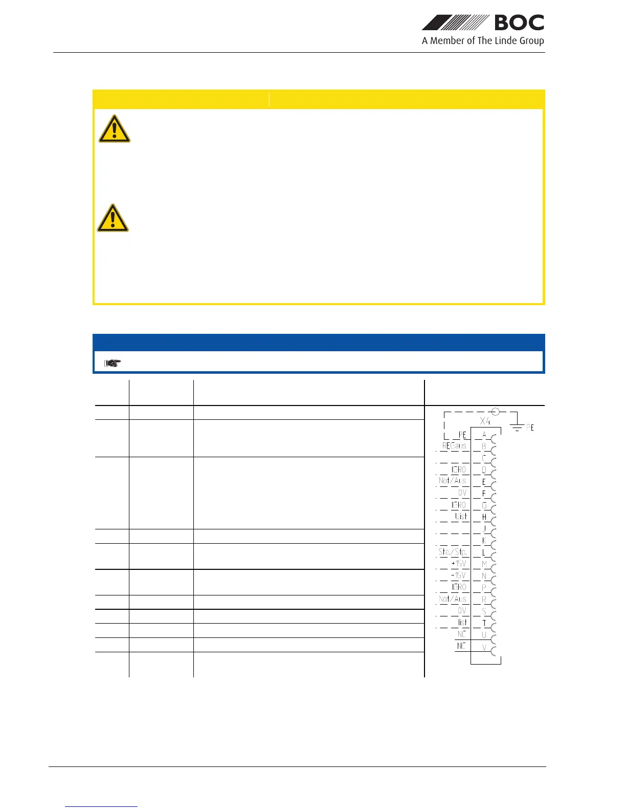
5.11.1 Automation interface
NOTE
These accessory components can be retrofitted as an option, see Accessories chapter.
Pin Input /
output
Description Diagram
A
Output PE Connection for cable shielding
D
Output
(open
collector)
IGRO Current flows signal I>0 (maximum load 20
mA / 15 V)
0 V = welding current flows
E
+
R
Input Not/Aus Emergency stop for higher level shut-down
of the power source.
To use this function, jumper 1 must be
unplugged on PCB M320/1 in the welding
machine. Contact open = welding current
off
F
Output 0 V Reference potential
G/P
Output I>0 Power relay contact, galvanically isolated
(max. +/-15 V / 100 mA)
H
Output Uist Welding voltage, measured against pin F,
0-10 V (0 V = 0 V; 10 V = 100 V)
L
Input Str/Stp Start = 15 V / Stop = 0 V
1)
M
Output +15 V Voltage supply (max. 75 mA)
N
Output -15 V Voltage supply (max. 25 mA)
S
Output 0 V Reference potential
T
Output Iist Welding current, measured on pin F;
0-10 V (0 V = 0 A, 10 V = 1000 A)
1
) The operating mode is given by the wire feed unit (the start / stop function equates to pressing
the torch trigger and is used in mechanised applications, for example).
 Loading...