11
Boy
Fig.2
Dear customer,
Congratulations on purchasing an Steinweg-Böcker-
Baumaschinen GmbH hoist, a reliable and innovative product
created through years of experience.
-
WORKING IN SAFETY: The following instructions
are essential for safety.
This OPERATING AND MAINTENANCE manual must be kept on
site by the foreman and must be accessible for consultation at
all times.
The manual is be considered an integral part of the machine
and must be kept for future reference (EN ISO 12100-2) until
the machine is scrapped. If it is damaged or lost, a replacement
copy can be requested from the hoist manufacturer.
The manual contains important information on site preparation,
installation, operation, maintenance and ordering of spare parts.
The installer and operator must have adequate experience and
knowledge of the machine.
To guarantee complete safety of the operator, safe operation
and a long service life, follow the instructions in this manual
and observe current applicable legislation regarding safety and
accident prevention in the workplace (use of suitable footwear,
clothing, hard hats and safety harnesses, proper installation of
railings around drops, etc.).
-
It is strictly forbidden to modify the steel structure
or working parts of the machine in any way.
Steinweg-Böcker-Baumaschinen GmbH will accept no
responsibility for failure to comply with legislation and standards
governing the use of hoisting equipment, in particular: improper
use, incorrect power supply, inadequate maintenance,
unauthorised modifications, tampering and/or damage and partial
or complete failure to observe the instructions contained in this
manual.
-
Steinweg-Böcker-Baumaschinen GmbH reserves
the right to modify the characteristics of the hoist and/
or the contents of this manual without any obligation to
update previous machines or manuals.
1. GENERAL DESCRIPTION
-
Warning: Use of lifting equipment requires great
skill and care. The hoist must be used by skilled and
properly instructed personnel only.
-
1) The machine is designed exclusively for lifting
materials and for use on building sites.
-
2) The machine must not be used for lifting people
and/or animals.
-
3) The machine must not be used in potentially
explosive atmospheres or underground.
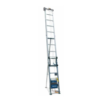
The machine consists essentially of (fig. 1):
- Drum type winch fitted to reduction gear shaft (3), wire rope
(1), lift hook (2) and counterweight (10).
- Gearmotor consisting of a self-braking electric motor (4) and
an oil-bath reduction gear unit (14).
- Electrical system (5).
- UP position control lever (9).
- DOWN position control lever (17).
- Rotary frame (7) with telescopic arm (6), loocking handle (8) and
frame locking lever (11).
- Thermal overload (16) which stops the winch when the current
exceeds the nominal value (press to reset).
- The winch has three types of pendant control (15)
1.5 m lead direct pendant
30 m low voltage (24V) pendant.
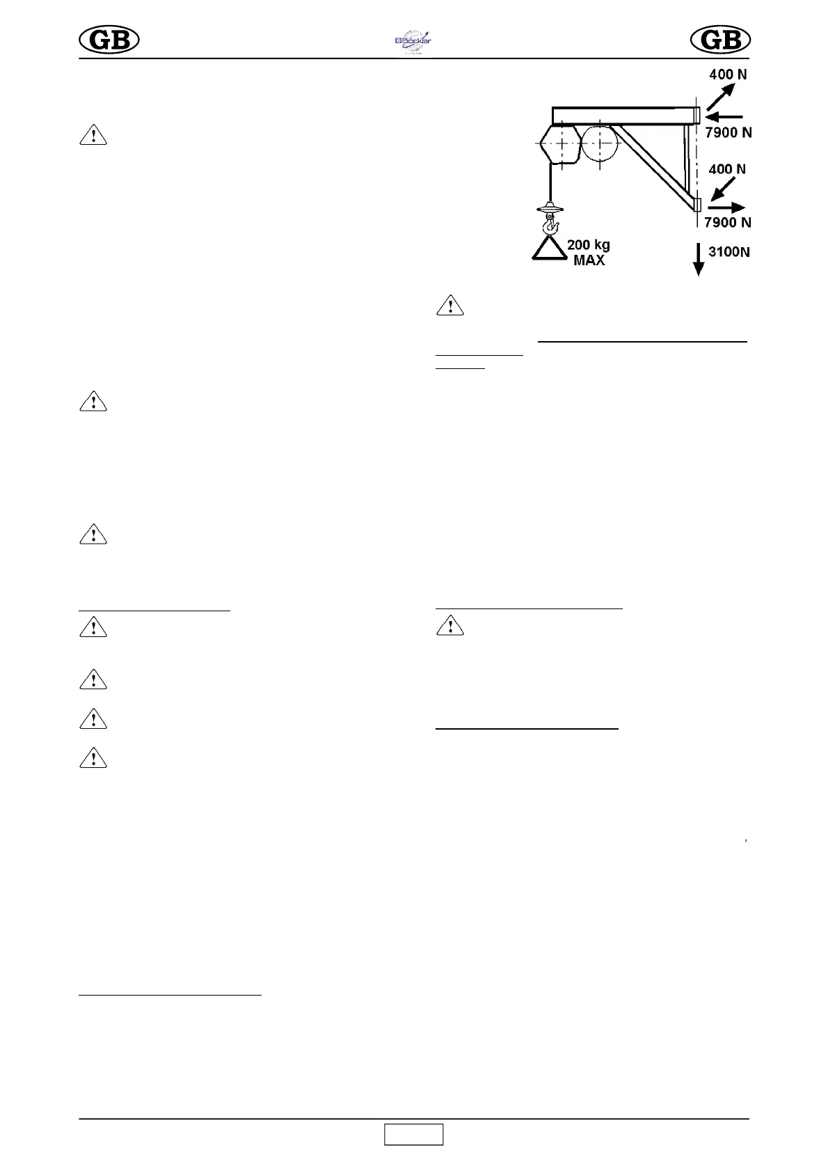
2. HOIST SUPPORT STRUCTURE
The structure on which the hoist is mounted must be able to
withstand the stresses generated during operation (fig. 2).
The 400 N force is perpendicular to the 5000 N force. Since the
hoist is able to rotate on the supporting hinges, these forces
must be verified in all possible positions of the hoist.
Steinweg-Böcker-Baumaschinen GmbH offers a wide range of
supports (see figures 7, 8, 9, 10, 11) for use on building sites, designed
to suitably transfer the stresses to the building structures.
-
IMPORTANT
The EC declaration of conformity enclosed with this
manual is valid only if components manufactured
exclusively by Steinweg-Böcker-Baumaschinen GmbH
are used
(hoist and support structures).
If this condition is not satisfied, this declaration is valid
only for the hoist.
The installer should compile a new EC declaration of
conformity, after verifying all requirements stated in
the Machinery Directive 2006/42/EC for the equipment
and support assembly.
The forces on the support couplings must be accounted for in
calculations for the supporting structures (scaffolding,
balconies, ceilings, etc.) made by a qualified technician.
If the hoist is to be mounted on scaffolding, the latter must be
adequately braced against wind (see fig. 12).
Follow the instructions provided for installation of the various
supports.
If supports with different capacities from the hoist are used,
the permissible capacity of the weakest element in the system
must be marked on the assembly in a clearly visible position.
2.1 PREPARING THE WORKPLACE
- The loading access area must be protected by a
rail at least 1 m high and with a foot stop.
- Make sure that the lifting run is free from obstacles and make
sure that no one can lean out from intermediate floors.
- Cordon off the ground loading area to ensure that no one
enters the area during lifting.
3. MOUNTING THE HOIST (fig. 1)
1) Only competent, trained personnel may assemble and ope-
rate the hoist.
Given the weight of the hoist, it must be transported and
installed by an adequate number of operators to avoid
hazardous situations.
2) The maximum working height (30 m) corresponds to the
gearmotor position, i.e. it is measured from the top hinge of the
support.
3)
Secure the support to the building and check the support pins
vertical alignment (12); then lift the locking lever (11) to insert the
frame bushings (7) onto the pins and fit the split pin retainer (13).
4) Fit the telescopic arm (6) to the frame (7) at its minimum extension,
screw on the locking handle and washer in the threaded hole through
its slot and tighten fully.
5) Ensure that the hoist is completely level by means of a spirit
level placed on the top plate of the drum. (fig. 1).
6)
The telescopic arm (6) allows a lifting excursion from the
axis of the pins of between 720 and 1120 mm.
7) When assembling on a trestle support, fit the telescopic arm (6) to
the carriage through the securing holes (fig. 12) using bolts and
locknuts. For the rest, follow the instructions for the trestle support.
5)
Insert the direct pendant control (1.5 or 5 m lead) plug in the
electrical panel (5)
and hook the spring clip of the steel cable
onto the ring on the electric panel to avoid pull on the electric
cable.
For the 24V low voltage pendant fix the electrical panel on the frame
(7) and insert the connector in the panel (5).
All pendant controls have 3 pushbuttons (Fig. 3):
O
R
I
G
I
N
A
L
T
E
X
T
 Loading...