The provided document is an original manufacturer's operating and maintenance instructions for Böcker material lifts, specifically the LMX and LHX series.
Function Description
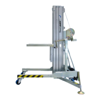
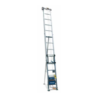
The LMX and LHX series are mobile lifting devices designed for material and installation tasks. They can be used in closed spaces and, under specific safety conditions, outdoors. The LHX series is an LMX lift equipped with an "electro-hydraulic drive."
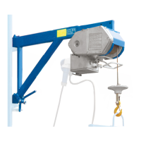
The primary function of these lifts is to raise and lower loads. For the LMX models, this is achieved by turning a crank handle clockwise to lift and anti-clockwise to lower. An integrated automatic brake holds the load when the crank handle is released. For the LHX models, the hydraulic winch is operated via a manual control valve: pushing the lever up lifts the load, and pushing it down lowers it. Releasing the lever automatically returns it to the middle position, shutting down the hydraulic winch and holding the load in place via a non-return valve and hydraulically operated brakes. A pressure relief valve prevents overloading of the hydraulic winch.
The lifts are designed to be mobile, featuring wheels for transport and castors for positioning. They are equipped with outriggers for additional stability during operation.
Important Technical Specifications
The document provides technical data for the LMX 500, LHX 330, and LHX 500 models.
LMX 500:
- Max. load: 500 kg
- Lifting height, crane fork at top: 4800 mm
- Lifting height, crane fork at bottom: 4350 mm
- Length of crane fork: 650 mm
- Width of crane fork: 560 mm
- Length of chassis: 1610 mm
- Width of chassis: 760 mm
- Width of chassis incl. outriggers: 1920 mm
- Height of mast: 1970 mm
- Length of transport: 765 mm
- Width of transport: 760 mm
- Unladen weight without outriggers: 202 kg
- Unladen weight with outriggers: 216 kg
- Standard power supply: 230V 50Hz (for LHX series, implied for LMX if electric)
- Cable recommendation: Ø 7 mm, single wire strength 1770 N/qmm, zinc coated according to DIN 3060, Section 20 + 22 VBG 14 UVV.
LHX 330 / LHX 500:
- Max. load: 500 kg (for both models)
- Lifting height, crane fork at top: LHX 330: 3375 mm; LHX 500: 4810 mm
- Lifting height, crane fork at bottom: LHX 330: 2880 mm; LHX 500: 4310 mm
- Length of crane fork: 585 mm
- Length of chassis: 1610 mm
- Width of chassis (centre of spindle): 1780 mm
- Height of mast: 1975 mm
- Length of transport: 765 mm
- Width of transport: 760 mm
- Width of crane fork: 560 mm
- Unladen weight without outriggers: LHX 330: 263 kg; LHX 500: 286 kg
- Standard power supply: 230V 50Hz
- Cable recommendation: Ø 7 mm, single wire strength 1770 N/qmm, zinc coated according to DIN 3060, Section 20 + 22 VBG 14 UVV.
Outdoor Usage Conditions:
- Load: 0 kg up to a maximum of 500 kg
- Wind force: Up to a maximum of wind force 3 (Beaufort scale)
- Surface of load: lengthways (of the chassis): 1.25 m²; crossways (of the chassis): 1.00 m²
- For LMX500 with electric glass suction unit: operation must be discontinued at wind force higher than 3 (19 km/h), and the area of the glass pane must be reduced to 2 m².
Usage Features
Installation and Commissioning:
- The lift must only be used on level, load-bearing, and oil-tight surfaces.
- The chassis front parts are folded down and secured with hexagon screws and nuts.
- For LHX models, the block tap at the hydraulic tank must be opened prior to commissioning.
- The crane fork can be fitted to either the underside or upper side of the carriage.
- Lateral outriggers must be attached for stability, lowered only to the extent that the castors maintain ground contact, and locked with locking bolts.
- The lift must be leveled on all sides using a spirit level.
- Prior to operation, the wire rope must be checked for damage, correct guidance, and winding.
- For LHX models, the electric equipment must be compatible with the local supply network.
Operation:
- The lift must only be operated on even surfaces, with all castor locks engaged, and never overloaded.
- It must not be wheeled around when loaded.
- Loads must be secured on the crane fork with appropriate equipment (e.g., lashing straps) and placed centrally.
- For LMX, the crank handle lifts and lowers the load, with an automatic brake. At least 2 winds of cable must remain on the drum when driving down loaded.
- For LHX, a manual control valve operates the hydraulic winch. The motor protection circuit breaker also serves as an emergency shut-off.
- The hydraulic shutoff valve must shut off the winch in the lowest position of the crane fork to prevent damage.
- After use or prolonged stops, the unit must be switched off via the circuit breaker and secured against unintended use.
Safety:
- Operation, maintenance, and repair must be carried out by authorized, qualified, and instructed technical personnel.
- The lift must be in technically good order; any malfunctions require immediate shutdown.
- Safety systems and locks must be checked by qualified personnel at regular intervals (at least annually).
- Persons must not stand below suspended loads or be in the working/hazardous area, except for the operator.
- Ladders must not be used on or at the lift.
- The extended lift must never be driven with a load.
- The lift must not be left unattended in operational condition or with a load.
- Sufficient safety distance must be maintained from electric lines and devices (at least 5 m for up to 200kV).
- The load center must never be more than 330 mm from the back of the fork.
- Strict adherence to UVV Regulations VBG 14 Lifting platforms is required.
- The unit must be secured against unauthorized use after final shutdown.
- Operators must be at least 18 years old, instructed, and demonstrate ability to the employer in writing.
- Warning lights, barriers, or safety posts should be used when operating in traffic areas.
- Protective clothing (helmet, glasses, gloves) must be worn.
Maintenance Features
Daily Checks:
- Wire cable and cable guidance (pulleys, pulley displacements)
- Correct winding of the wire rope on the rope drum
- Crane fork
- Rail profiles and rail guide (plastic rolls)
- Chassis with front components
- Manual winch or hydraulic winch
- Hydraulic functional components (hoses, screw fittings, motor, brakes, etc.)
- Castors and wheels
- Fixing elements (screws, nuts, bolts)
- Outriggers with supporting spindles
Regular Maintenance:
- Immediately discontinue operation if damage or signs of damage are present. Defective or damaged components must be replaced with original parts.
- Check the entire unit for deformation, damage, corrosion, oxidation, and tears in welding seams.
- Protect the lift from contamination, rain, and weather effects.
- Protect mast elements (aluminum) from dirt and rubbish.
- Treat the interior side of the mast with silicone spray.
- Check plastic rolls and pulleys for wear and tear.
- The crank handle winch thread must be greased at all times. Bearing bushes of drive shafts and drum hubs should be regularly oiled.
- Important: Do not oil or grease the brake mechanism.
- The lift must be inspected annually by a qualified person, or more frequently depending on operating conditions.
- Stickers on the lift must be clearly visible and recognizable.
Malfunction Procedures:
- Before work, check if mast components run in the correct sequence (carriage lifts, then front mast, then second mast, etc., reversed for lowering).
- Potential causes of malfunction include: jumped wire cable, incorrectly wound wire rope, defective pulleys/bearings, dirt/rubbish between mast components, damaged mast cable/carriage, overloading, or one-sided load.
- The cause of the malfunction must be removed, and the correct sequence restored. Böcker Maschinenwerke GmbH can be contacted for queries.