06/058
2.2.2 ACT frequency inverter series
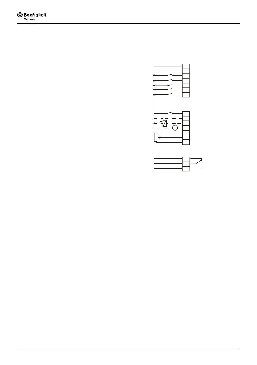
The following illustration shows a possible solution of connecting the control terminals
of the ACT frequency inverter in hoist and lift application.
GND 24V
S1OUT
MFO1A
+10V / 4mA
MFI1A
GND 10V
1
2
3
4
5
6
7
210A
+24V / 180mA
GND 24V
S1IND
S2IND
S3IND
S4IND
S5IND
S6IND
X210B
1
2
3
4
5
6
7
V
+
+
-
controller release / error acknowledgement
lifting - start clockwise
lowering - start anticlockwise
positioning
frequency limitation 1
frequency limitation 2
holding brake
actual frequency
1
2
3
S3OUT
X10
fault message
{
reference speed
{
Note: The connection diagram describes the standard configuration of the con-
trol terminals. According to the requirements in the application deviating
connection possibilities are to be configured by the freely programmable
combinations.
The control signals at the terminals X210A.6 and X210A.7 in the above
connection diagram are for example linked with the software module for
speed sensor evaluation in the configuration 260.

 Loading...


