06/0514
4.2.4 Stopping the drive
Stopping the drive up to standstill of the drive can be parameterized via various time
constants. The parameterized
Stopping behavior 630 as a function of the digital sig-
nals
Start clockwise STR and Start Anti-clockwise STL is to be observed.
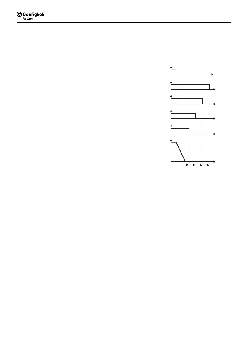
1. If the internal reference frequency
(output of the ramp function) is smaller
than the
Frequency threshold 809
(time Tc), the sequence of the shut-
down function starts. The percentage is
set relative to the
Maximum frequency
419.
2. After
Time t13 806 the signal of
the holding brake is deactivated. To re-
duce wear and tear, this time should be
set in such a way that the drive is at a
standstill before the brake closes.
If the signal is to be deactivated when
the drive is still rotating, this time is to
be set to zero and the
Frequency
threshold
809 increased if need be. A
long reaction time of the mechanical
brake in closing can thus be compen-
sated.
3. After expiry of
Time t12 805 the
current monitoring is deactivated. This
time constant should be at least equal
to the reaction time of the mechanical
brake in closing.
t
13
t
11
t
15
t
12
T
c
start command
activation
safety contactor
activation
holding brake
motor current
monitoring
motor current
reference
frequency
frequency
threshold
4. After expiry of
Time t11 804 the power parts of the frequency inverter are
blocked. The current in the motor goes to zero.
5. After expiry of
Time t15 807 the signal to close the safety switch is deacti-
vated. As the deceleration time of a relay is normally distinctly lon
ger than the time
needed for the current reduction, this time can remain at the figure zero (factory
setting) in most cases.

 Loading...


