06/05 9
3 Commissioning of the frequency inverter
3.1 Switch mains voltage on
After the installation work has been completed, all the control and power connections
should be checked again before the mains voltage is switched on. If all the electrical
connections are correct, please ensure that the release of the frequency inverter has
been switched off (control input S1IND open). After the mains volta
ge has been
switched on, the frequency inverter makes a self-test and the relay output reports
"Fault".
After a few seconds, the frequency inverter completes the self-test, the relay reacts
and reports "no fault ".
In the state upon delivery and after the settin
g of the factory settings, the guided
commissioning is automatically triggered. The control unit shows the menu point
“SETUP“ from the menu branch CTRL.
Danger! The functionality of the extended brake control described in this applica-
tion manual and the connection of the holding brake to the control termi-
nals of the frequency inverter are to be checked at the start of the com-
missionin
g. The guided commissioning is to be done with the holding
brake closed.
3.2 Setup with the control unit
The guided commissioning of the frequency inverter is described in the operating in-
structions for the configurations 110, 210 and 410. According to the operating instruc-
tions, the
uided commissionin
is to be done observin
the safety information and
further directives to be observed.
Attention! The guided commissioning contains the function for parameter identifica-
tion. The parameters are determined and set accordingly by a measure-
ment. Before the start of the measurement, the motor should not have
been operated, as a part of the machine data is dependent upon the
operating temperature.
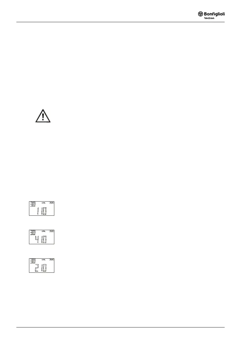
Configuration 110, sensor-less regulation
Configuration 110 contains the functions for variable-speed controls of a 3-phase
machine in a large number of standard applications. The motor speed is set ac-
cording to the V/f characteristic in accordance with the ratio of voltage and fre-
quency.
Configuration 410, sensor-less field-oriented control
Configuration 410 contains the functions for sensor-less, field-oriented control of a
3-phase machine. The current motor speed is determined from the present cur-
rents and volta
ges in combination with the machine parameters. Parallel switching
of 3-phase motors is only restrictedly possible in this configuration.
Configuration 210, field-oriented control
Configuration 210 contains the functions for speed-controlled, field-oriented con-
trol of a 3-phase machine with speed sensor feedback. The separate control o
f
torque and flux-forming current enables a high drive dynamic with a high torque
of load. The necessary speed sensor feedback leads to a precise speed and torque
behavior.
After successful completion of the SETUP routine, the matching configuration 160, 260
or 460 for the extended activation of a holding brake and the function for automatic
load detection in hoist application is selected via the parameter
Configuration 30
from the menu branch PARA.

 Loading...


