06/05 7
2.2 Control inputs and outputs
The modular structure of the frequency inverters enables a wide range of applications
on the basis of the available hardware and software functionality. The functionality o
the control inputs and outputs described in the brief manual and the operating instruc-
tions are extended in the configurations 160, 460 and 260.
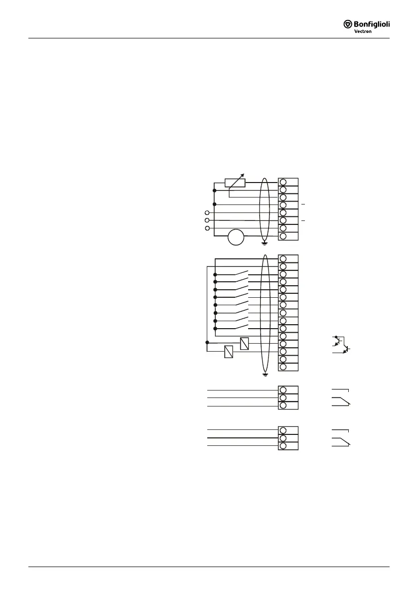
2.2.1 VCB frequency inverter series
The following illustration shows a possible solution of connecting the control terminals
of the VCB frequency inverter in hoist and lift application.
+10V / 10mA
1
2
3
4
5
6
7
8
GND 10V
+
+
+
} S1INA (U)
} S2INA (U)
} S3INA (I)
S1OUTA (I)
X211
9
10
11
12
13
14
15
S7IND
S8IND
+24V ext.
S1OUT
S2OUT
GND 8V ext.
+8V ext.
1
2
3
4
5
6
7
8
X210
+24V / 150mA
GND 24V
S1IND
S2IND
S3IND
S4IND
S5IND
S6IND
1
2
3
X209
S6OUT
mA
+
-
+
-
+
-
fault message
{
frequency contact
operating message
FUF
lifting - STR
lowering - STL
positioning - DSS1
DSS2
frequency limitation - FFS1
frequency limitation - FFS2
RESET
reference speed
{
X460
holding brake
{
1
2
3
S3OUT
Note: The connection diagram describes the standard configuration of the con-
trol terminals. According to the requirements in the application deviating
connection possibilities are to be configured by the freely programmable
combinations.
In the above connection diagram the holding brake is connected for ex-
ample with the strip X460 of the extension module EAL-1.

 Loading...


