Voorhout • Groningen • Weert • Hoogerheide T +31(0)88 7865800 I elsto.eu
Quick Start Guide
Agile
50 05/2013
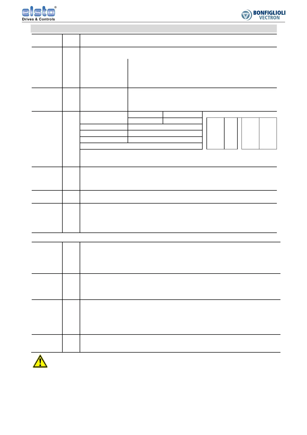
Technical data of control terminals
Volta
e
outputs
X11.1 DC 24 V, Imax =100 mA. Appropriate GND: X11.2.
X13.4 DC 10 V, Imax =2.3 mA (dependent on level of DC 24 V voltage input), Imax = 8.2 mA
Voltage
inputs
X13.1
Input for external voltage supply. Connect the ground potential of the external voltage
supply to X13.2 (GND).
Input voltage range DC 24 V ± 10%
Rated input current Max. 1.0 A (typical 0.45 A)
Peak inrush current Typical < 15 A (max. 100 μs)
External fuse Via standard fuse element for rated current, characteristic: slow
Safety Safety extra low voltage (SELV) according to EN 61800-5-1
Digital
enable
inputs
X11.3 Signal levels Low DC 0 ... 3 V, High DC 12 ... 30 V
X13.3 U
max
DC 30 V (10 mA at DC 24 V)
Input Resistance 1.8 kΩ
Response time STO is activated 10 ms after triggering.
Digital
inputs
X11.4
Signal levels
PNP input High ≥ DC 10 V Switch-over PNP/ NPN
X11.5 NPN input High ≤ DC 5 V X11.4
X11.5
X12.1
X12.2
X11.6
P559 X12.3
X12.4
P452
P562
X12.1 U
max
DC 30 V (6 mA at DC 24 V)
X12.2 Input resistance
3.9 kΩ
Response time 2 ms
PLC compatibile
X11.6
X12.3
X12.4
Æ
Æ
Æ
Digital input/ output
Multifunction
Multifunction
Digital
outputs
X13.5 U
out
DC 22 V (DC 15 ... 30 V)
I
max
100 mA (I
max
is reduced if further control outputs are used.)
Overload- and short circuit-proof, overvoltage- protected.
X11.6 Æ Digital input/ output
nalo
inputs
X12.3
X12.4
Æ
Æ
Multifunction
Multifunction
Digital
input/
output
X11.6 Default: digital input. —► Refer to table row “Digital inputs”.
Can be configured as digital output by means of P558.
Output: U
out
DC 22 V (DC 15 ... 30 V)
I
max
100 mA (I
max
is reduced if further control outputs are used.)
Overload- and short circuit-proof, overvoltage- protected.
Multifunction
Di
ital/
analog
input
X12.3
Default: analog voltage input. Can be configured as analog current input or digital input by
means of P452.
Voltage input DC 0…10 V (R
i
= 78 kΩ) Resolution 10 Bit R
i
: input
resistance
Current input DC 0…20 mA (R
i
= 250 Ω) Resolution 9 Bit
Digital input Æ Refer to table row “Digital inputs”.
Di
ital/
analog
input
X12.4
Default: digital. Can be configured as analog input MFI2A by means of P562.
Voltage input DC 0…10 V (R
i
= 78 kΩ) Resolution 10 Bit R
i
: input
resistance
Current input DC 0…20 mA (R
i
= 250 Ω) Resolution 9 Bit
Digital input Æ Refer to table row “Digital inputs”.
Di
ital/
analog/
frequency/
pulse train
output
X13.6
Default: analog. Can be configured as digital output, analog output, frequency output or pulse
train output by means of P550.
Analog signal: pulse width modulated, f
PWM
= 115 Hz. Frequency signal: f
max
= 150 kHz.
Digital output: U
out
DC 22 V (DC 15 ... 30 V)
I
max
100 mA (Imax is reduced if further control outputs are used.)
Overload- and short circuit-proof, overvoltage- protected.
Relay
output
X10
Maximum contact load:
make contact: AC 5A/ 240V, DC 5A (ohmic)/ 24V,
break contact: AC 3A/ 240V, DC 1A (ohmic)/ 24V
Caution!
The digital inputs and the DC 24 V input can withstand external voltage up to DC 30 V. Avoid higher voltage levels.
The temperature monitoring must be sufficient insulated towards the motor winding.

 Loading...


