EN
30
Installation
www.bora.com
Tepan stainless steel grill CKT
5
4
3
2
2
1
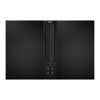
Fig. 4.33 Securing the Tepan stainless steel grill
[1] Angled plate
[2] Screws
[3] Washer
[4] Screw (60 mm)
[5] Mounting bracket
INFO Before the Tepan stainless steel grill can be laid in
the cut-out, the 4 angled plates [1] must be fitted.
Secure the cooktop using the four mounting brackets
[5].
To do this, tighten the mounting brackets with the
screws [2] and [4] using the washer [3] with max.
2 Nm.
Do not use a cordless screwdriver or similar electrical
device to secure the Tepan stainless steel grill
Check that the alignment and installation height are
correct.
4.12 Connecting external switch
contacts
INFO The Home In and Home Out external connections
must only be connected by a certified specialist.
The specialist also assumes responsibility for the
proper installation and commissioning.
When using Home In and Home Out, you will require the
relevant documents for the external switch devices in
order to ensure safe device connection and operation.
The following switch contacts can be used:
Contact Function Connection
Home In Cooktop extractor on/off
connection for external switch
contact (contact closed: cooktop
extractor on)
24V DC
100 mA
Home Out
Electrically isolated contact for
controlling external installations
depending on the operating status
of the cooktop extractor (cooktop
extractor on: contact closed)
maximum
250 VAC/30 VDC,
2.5A
Tab. 4.5 Switch contacts
INFO The Home In contact can be used for external
safety devices (e.g. window contact switches). If
the switch is open, the cooktop extractor is off.
INFO
No window contact switches may be installed that
interrupt the control unit power supply (phase
separation). Only the built-in interface is to be used.
Preparing the control unit
1
2
3
4
5
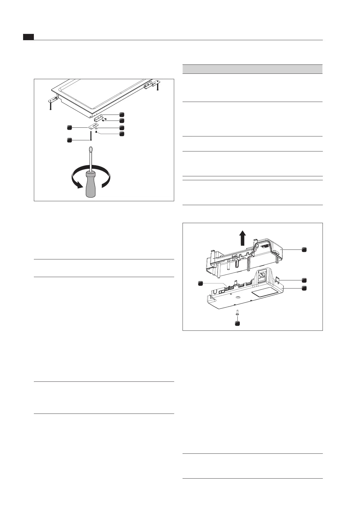
Fig. 4.34 Opening the control unit housing cover
[1] Housing cover
[2] Locks
[3] Housing subshell
[4] Screw
[5] Electronic unit
Ensure that the control unit is disconnected from the
power supply.
Loosen the screw [4] on the housing cover [1].
Carefully release all locks [2] with a slotted screw
driver.
Remove the housing cover [1] from the housing
subshell [3] by lifting it up.
Do not touch the electronic unit [5].
INFO The electronic unit can contain residual charge.
You must therefore be careful not to touch the
exposed contacts on the electronic unit.